Tebis V4.1 R7 full cracked licesne
$ 200.00
Tebis 4.1 Release 7 for even better collision checking and less re-machining
Your benefits at a glance:
- Solid technology: Now easily select faces
- Tool simulation: Check any geometries with just a few mouse clicks across NCJobs
- Prevent collisions during CAM calculation: Now totally account for the machine head in all strategies
- 3-axis finishing: High-quality milling results even faster
- 5-axis simultaneous roughing of pockets and surfaces: Reduce machine run time even more, low-wear plunge movements
- Improved usability: Interactively display the contact point between milling tool and part surfaces and analyze cutting conditions at a glance
- Laser drilling: An even shorter calculation and machine run time
Description
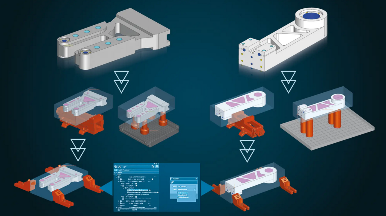
CAD – Parametric design
Conveniently control changes with user parameters
Every imported data set needs to be prepared for CAM programming in design. This usually takes many individual work steps: Bores for clamping systems must be placed, tilt axis systems defined, fill surfaces designed, blanks created, connection points for setups generated, clamping devices positioned and retract planes defined. These many individual steps can be highly automated in Tebis using parametric CAD templates. These templates can be extended as needed and can be adapted to meet customer-specific requirements. Users can still be highly flexible: Changes like selecting a different clamping system can now be controlled directly and conveniently with the user parameters in the object tree.
CAD – Active surface design
Precise results when trimming deep-drawing and bending parts
The “Create development curves” function can be used to quickly and easily determine theoretically designed trim edges for flanges on deep-drawing and bending parts. The material thickness of the component and the location of the neutral fiber are accounted for – and the result is highly precise, with no manual reworking necessary. The quality of the resulting curves corresponds to that of the original curves.
Multiple calculation modes cover different use cases.
Multiple calculation modes cover different use cases.
CAM – Automation
Shorter programming time thanks to improved NCJob technology
Your CAM programs are finished more quickly with these new features:
Take advantage of the opportunity to automatically apply interactively defined milling areas from previous NCJobs in milling.This allows you to reduce manual intervention in CAM programming and calculate entire NCJob sequences at once. CAM programming is also significantly simplified – you can easily manage combined machining operations in an end-to-end CAM template.
And you can avoid issues like superfluous calculation time by conveniently calculating multiple NCJobs simultaneously up to “Areas calculated” or “Sorting executed” status.
CAM – Drilling
Flexibly use special cutters
When using combined special cutters with several cutting edge areas of different diameters, only the diameter of the active cutting edge determines whether the tool is suitable for the specific machining task. This enables highly flexible use of special cutters for drill-milling and thread milling in bores and circular pockets – regardless of the diameter of the largest cutting area. The plausibility check also only accounts for the properties of the cutting area actually used.
CAM – Milling
Optimal cutting conditions for roughing rotationally symmetrical parts
A real plus for combined turning/milling operations: In addition to cylindrical parts, tapered parts such as screw conveyors can now also be machined with high efficiency. The tool first roughs the part to the maximum possible depth with a low stepover and large downfeed in a single pass. Then it machines the residual stock from bottom to top with a smaller cutting depth – precisely to the stock allowance. This procedure reduces tool wear and ensures a high material removal rate on the machine. The user can easily program the final finishing operation with a special function: Only the strategy is replaced – the system does the rest.
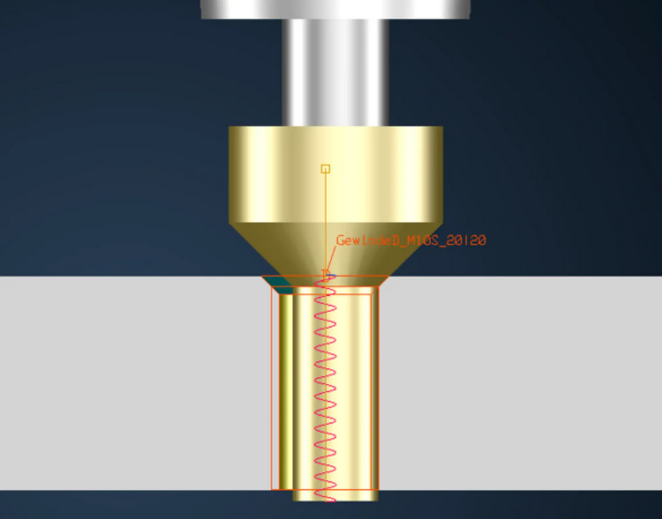
Safely manufacture external threads
External threads can now be quickly manufactured in just one NC program – including stud, chamfer and undercut This gives parts manufacturers even more options for programming toolpaths quickly, completely and safely in a simulation-supported CAM system.
Efficiently machine planar areas
It’s usually more cost-effective to machine the planar areas of a part after hardening with a smaller stock allowance than the non-planar areas Special tool types like large insert mills can then be used for this step. Tebis therefore offers a new function that automatically detects purely planar areas within selected part surfaces without the need to further subdivide the part.
Automatic tilt direction calculation with circle-segment cutters
This new function greatly simplifies the programming of multi-axis toolpaths for pre-finishing and finishing with circle-segment cutters, also known as “barrel cutters”. It automatically determines the best tilt direction for manufacturing the machining area completely free of collisions. The function simultaneously calculates the optimal contact point at the surface boundary to ensure the maximum possible material removal. Machining is indexed or 5-axis simultaneous: The user can independently specify the preferred variant or can leave the decision up to the system.
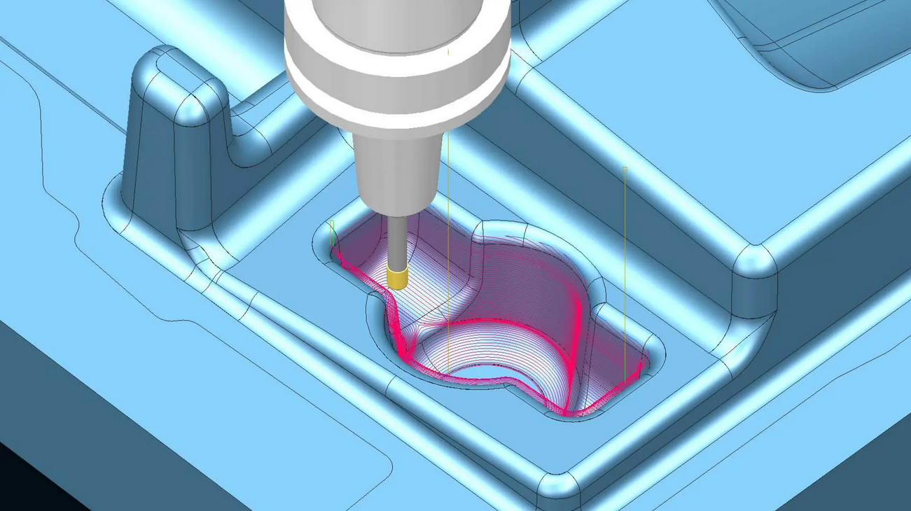
Continuous, automated 3-axis finishing of flank surfaces, transition areas and bottom surfaces with no offset
Geometries with steep flank surfaces, straight bottom surfaces and entrance and exit radii – like ribs and slots – can now be machined automatically and with a uniform step and 3-axis Z-constant machining with the “Finishing surfaces” function – without retract movements, without extra design effort and at outstanding quality.
CAM – Lathe
Turning with convenient cutting off of the part
Parts can be cut off from bar stock with a special function for automated machining on lathes or turning-milling centers. You can quickly and easily define the optimal cutting conditions for feed rate and speed on material exit. You can easily cut the part off straight or finish its contour at the same time without having to design an auxiliary geometry. You can deburr the part and turn the bar side flat during cutoff. This allows you to immediately manufacture the next part with the bar stock. The cut-off part can be transferred to the second spindle or taken up by the part gripper/catcher – with automatic control and reliable simulation.
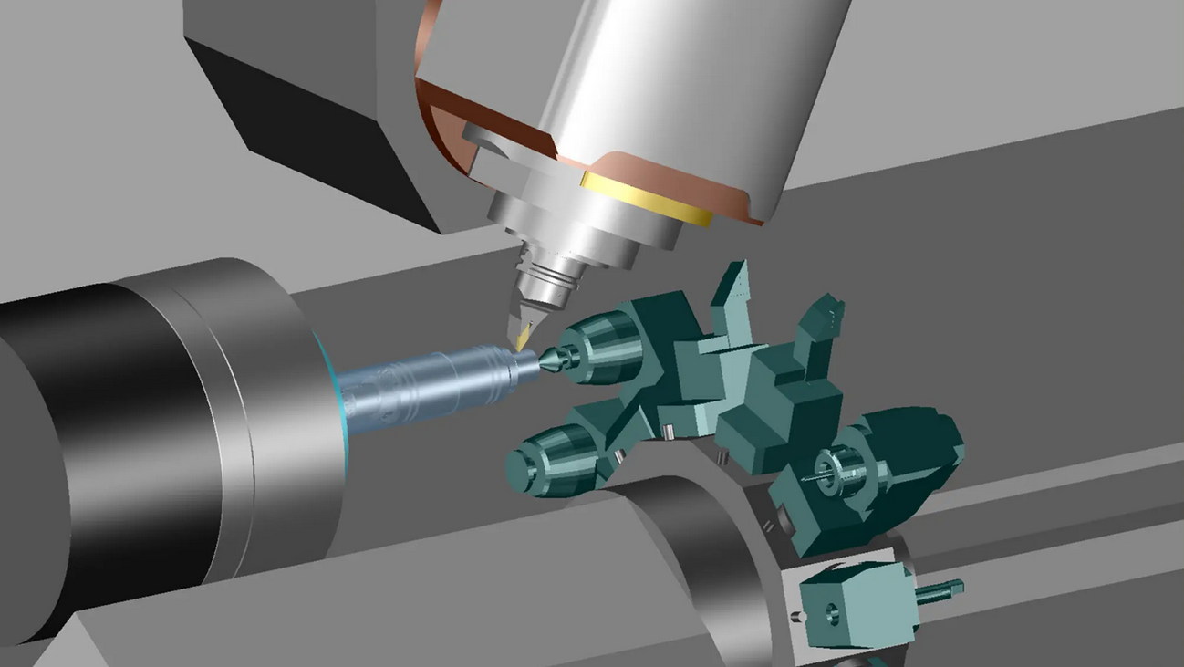
CAM – Machine technology
Improved support for multi-channel machine tools
This innovation is especially advantageous for manufacturing companies that rely on combined turning/milling operations, especially if the components to be machined have a high milling fraction: Tebis can now be used to program toolpaths for sequential processing on machines with multiple tool and component holders. The individual steps – such as milling with a milling head or turret, stabilizing with a centering tip or clamping with a sub spindle – can be combined in any way. All tool and component holders are stored in the virtual Tebis process libraries: These can be interchanged quickly and flexibly in programming. As always in Tebis, all system components are fully accounted for in collision checking and simulation. Programming is as easy as can be, following Tebis’s stringent and proven programming logic. Tebis automatically generates NC code for any machines and supports all control-specific program structures, such as Gildemeister structure programs.
CAM – Job planning
Complete collision control with material removal simulation
Material removal simulation ensures safe and reliable collision control. The actual material on the model is reliably accounted for at all times during machining and is checked against both the tool and all machine components. The blank is updated in each machining step.
Related products
-
Nikon CMM-Manager 3.5 cracked
$ 180.00 Add to cart Quick View -

TAJIMA DG/ML 16 By Pulse Embroidery Design Systems cracked version
$ 150.00 Add to cart Quick View -
Sale!

RESISTANCE & PROPULSION SUITE
Original price was: $ 3,500.00.$ 150.00Current price is: $ 150.00. Add to cart Quick View -
Sale!

OmniTrader 2016 Professional Edition with OmniPilot, DL cracked
Original price was: $ 1,995.00.$ 130.00Current price is: $ 130.00. Add to cart Quick View -
GPRSIM v3.0 cracked version
$ 130.00 Add to cart Quick View -

ETAP 14.1 cracked version download
$ 140.00 Add to cart Quick View -
Sale!

ZEISS PiWeb 8.6 cracked version
Original price was: $ 200.00.$ 140.00Current price is: $ 140.00. Add to cart Quick View -
Sale!
Intergraph Smart 3D 2016 cracked version
Original price was: $ 180.00.$ 135.00Current price is: $ 135.00. Add to cart Quick View -
Sale!
DESIGN SUITE cracked version
Original price was: $ 8,000.00.$ 250.00Current price is: $ 250.00. Add to cart Quick View -
Sale!
Wilcom DecoStudio E3 cracked with dongle emulator
Original price was: $ 2,000.00.$ 120.00Current price is: $ 120.00. Add to cart Quick View