SpatialAnalyzer 2022.2 full cracked license
$ 160.00
SpatialAnalyzer is the premier portable metrology software solution for large-scale applications. SA is an instrument-independent, traceable 3D graphical software platform that makes it easy for users to integrate data from multiple instruments and perform complex tasks simply, ultimately improving productivity. Click below for watch a video that will introduce you to the power of SA.
Description
User Interface Improvements
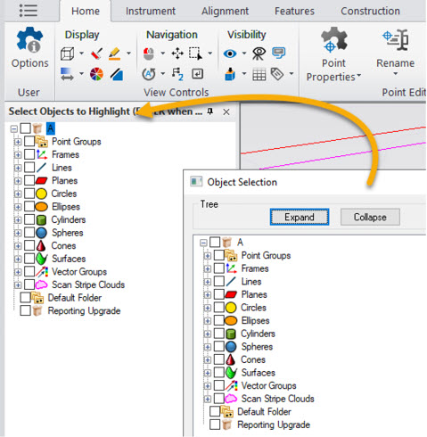
Added Tree Selection
The F2 selection window has been integrated directly into the SA Tree bar as a new dynamic selection panel. This allows direct access to multi-select options from a filtered list of relevant items, when selection is needed.
 Click here to view on YouTube
Import Improvements
New CAD Import Libraries:
The following updated support is now available:
- Autodesk Inventor 2022
- Creo 8.0
- FBX 7500
- NX 2007
- Parasolid 34
- Solid Edge 2022
- SolidWorks 2022
Inspection Improvements
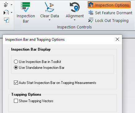
Added Inspection Options
There are now basic configuration options for inspection which allow you to choose between the Inspection bar and Toolkit Inspection panels and offers an option to automatically open the inspection bar when trapping begins.
Expanded Offset Plane References
In prior versions Offset Planes were always based upon a reference plane. In this version any objects base frame can be used as the reference. This expands their use by allowing an offset plane to be built from a dynamic frame for example.
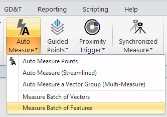
Added Auto-Measure Batch of Features
Auto-Measure >> Measure Batch of Features to support the automated measurement of Compare to Nominal GR-Features selection.
Currently, it allows to measure a list of circles and/or slots by Nikon APDIS MV400 Laser Radar. See more details in the instrument section.
GD&T Improvements
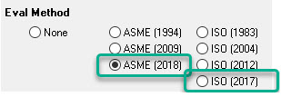
Added support for ASME 2018 and ISO 2017
Options are now available to have GD&T feature inspection conducted using the more recent standard definitions. These options can be found in the User Options >Analysis>GD&T Options
Added Control Over Diameter Tolerances
Added clarification to plus/minus tolerance modes of operation:
- PlusMinus. Will apply tolerances relative to the reference feature (as nominal).
- PlusMinusWithNominal. will apply tolerances relative to user defined reference value.

Cloud Based Inspection
Boundary Points
Added Right-Click option to Generate Boundary Points Clouds from a Scan Stripe Cloud. The boundary points define the extents of each scan line and can be used for edge or feature identification.
Real-Time Meshing Improvements
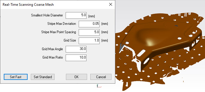
Real-Time Meshing has been significantly improved. Changes include greatly improved stability with laser trackers based scanners, leading line and cloud visualization as you scan. Greatly improved density and save sizes as well as improved settings and density controls.
Uncertainty Calculations
Modified uncertainty model for laser trackers
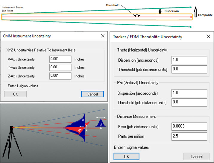
Modified uncertainty model for laser tracker (polar instruments) to eliminate singular behavior of uncertainty assessment when the measurement approaches polar points. Although this singular behavior accurately emulates the motor encoders, in practice the uncertainty is better modeled as:
Distance measurement uncertainty -> Error along line-of-sight(LOS)
THETA (Horizontal) uncertainty -> Error orthogonal to LOS in the horizontal plane
PHI (Vertical) uncertainty -> Error orthogonal to LOS in the direction of positive PHI
Consider sighting through a telescopic sight directed towards the measurement. The angular error is now computed with respect to this shot line.
Modified uncertainty model for PCMM Arms
The uncertainty parameters for an arm model have been simplified to an XYZ uncertainty with respect to the instrument base.
Added capability for setting XYZ uncertainties for PCMM instruments so that XYZ component uncertainties can be determined during USMN operations.
Reporting Improvements
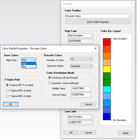
Added ability to reverse colors in Discrete Colors mode. Now, red color can be picked for high and blue for low.
