


Primtech 3D V18 SP2 cracked license software
180 $
Primary Technology CAE System for
CAD Design of High-Voltage Switchgear
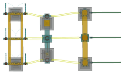
Primtech is the CAE system for use with primary technology for the design, construction, documentation and management of switchgear (substations).
High-voltage equipment, subsidiary constructions, cable ducts, cables, pipes, terminals on to roads and fences – these are all simply selected from a comprehensive, extensible library, and placed, as intelligent 3-D-objects, on a voltage-dependent grid.
The primtech evaluation functions and the automatic generation of CAD drawings relieves the designer of routine tasks, and helps to avoid expensive, time-consuming errors.
Benchmark tests have shown that primtech users are more than 15 times faster in some phases of the design of a switchgear project than when other, conventional CAD software tools for designing substations are used.
Users all round the world are enthusiastic about the functionality, which has grown over years and which offers project managers the quick overview they need to make the right decisions.
Description
What’s new in primtech 18 SP2:
OSR Technology has been optimized – within point cloud
In our OSR Technology – from a point cloud to a substation BIM model – our famous conductor recognition has been optimized even further and can now recognize conductors in point clouds even better. The conductor recognition plays a crucial role in the OSR Process as the first phase of the process and assists in the further automation.
Besides this, our innovative OSR Technology has, in general, been extended with new features and the input screen has been optimized. The results list can now be filtered according to additional attributes (e.g. Symbol type, Manufacturer …).
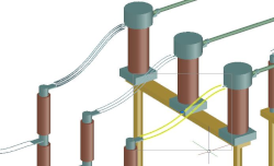
New Feature – Realistic Wires with Advanced Wire Mode
A new option has been introduced and can be called up on the wires – Curvature Type Advanced Modus. This modus allows the modifying of the position and curvature of the wires in space using grips (blue points). Any number of control points (grips) can be added or deleted. The entry tangent on both ends of the wire can be defined freely.
New Feature in Wire Connection Configurator – Number of Wires, Layout, Sag
The number of wires can be chosen between 1, 2, 3, 4, 6 and 8 wires. New is the wire layout – circular or linear. There is also the possibility to set the rotation offset of the wires in degrees. The sag of the normal wire can be set to 2 decimal points.
Lightning Protection according to IEEE 998
The lightning protection calculation according to IEEE 998 Standard is now more comfortable to use and can be selected directly in the input dialog.

Adjustments to HV-Cable and Conduits
The feature to insert HV-Cable and Conduits has been extended. The minimum bending radius can now be set to a value greater than that in the library. Additionally, a default radius can be set. If the situation allows, the default value will be used. If it does not fit, the largest fitting radius will be chosen until the minimum bending radius is reached. The desired radius for a segment can now be manually set.
New Import and Export Features in primtech + Drawing Converter
The new Drawing Converter is now available and optimizes the import of 3D geometries – “Import 3D Symbol”. E.g. for data originally created in MicroStation – and imports into primtech as DWG.
The new Drawing Converter allows as well the export, especially for Revit, Navisworks and Relux, using new default configurations. For example, matchcodes are included in the block, xref are bound and there are no longer problems with non-uniform scaled blocks.
Product Data Model
A high-voltage switchgear is saved in primtech as an integrated product data model, consisting of detailed 3-D geometry and of metadata. In accordance with the single-source principle, each item of information is present precisely once. Connectors are available for product-specific data relating to the substation displayed in the CAD system – the SAP/R3 connector, for example.
PLM – Product Lifecycle Management
primtech offers comprehensive support throughout the entire life-cycle of an installation, from the approvals planning stage, through the preparations for implementation and on to full operation and additions to the existing plant. Design variants can be managed and evaluated.
Related products
-

Intergraph PV Elite V21 cracked version
140 $ Add to cart Quick View -

AGTEK Earthwork 4D Suite 1.20 cracked
200 $ Add to cart Quick View -
Sale!

DESIGN SUITE cracked version
Original price was: 8,000 $.250 $Current price is: 250 $. Add to cart Quick View -

GPR-SLICE v7.0 cracked radar software
160 $ Add to cart Quick View -

NAPA 2013 Ship Design Software
150 $ Add to cart Quick View -
Sale!

Intergraph TANK NEW cracked version
Original price was: 180 $.150 $Current price is: 150 $. Add to cart Quick View -

ThinkDesign Suite 2015.2 64bit full cracked
150 $ Add to cart Quick View -

SOCET GXP 4.2.0 cracked full version
160 $ Add to cart Quick View -

Lantek Workshop (Manager, Wos, Capture)
150 $ Add to cart Quick View -

PointSense Total Package cracked version
200 $ Add to cart Quick View