Home » Shop » AxSTREAM Suite V3.6 by SoftInWay cracked
AxSTREAM Suite V3.6 by SoftInWay cracked
140 $
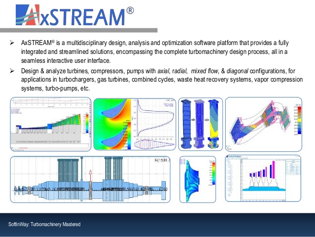
AxSTREAM Software Platform
The AxSTREAM software platform for multidisciplinary design, analysis and optimization provides an integrated and streamlined approach to turbomachinery design. This software solution encompasses the complete process of design for radial, axial and mixed flow turbomachinery. This includes turbines, compressors, blowers, pumps, fans, rotors, bearings, secondary flows, and cooling.
AxSTREAM already provides over 300 global clients with the tools needed to make their projects a success. Each module seamlessly integrates with one another so you can use AxSTREAM as your one stop shop or to assist you with a specific part of your design. AxSTREAM’s capabilities and features include:
The Preliminary Design set of modules includes:
Solution Generator that is used to produce a number of flow path geometries (solutions) for subsonic, transonic and supersonic flows that satisfy user-defined boundary conditions and geometric parameters within given constraints while accounting for real fluid properties (See Fluid Toolbox);
Design Space Explorer to review machine characteristics (geometry, performance, flow conditions) for all the designs generated;
Post-Design tool to further optimize the selected geometry.
Turbomachines of Interest
Depending on the license(s) available, machines that can be created using the Preliminary Design modules of AxSTREAM include:
Axial turbines
Axial compressors
Axial pumps
Single-stage axial fans / blowers
Multi-stage axial fans
Axial hydraulic turbines
Single-stage radial turbines
Multi-stage radial inflow turbines
Multi-stage radial outflow turbines
Radial compressors
Radial pumps;
Single-stage radial fans / blowers
Multi-stage radial fans
Radial hydraulic turbines
Radial-axial turbines
Axial-radial compressors / pumps
Mixed-flow (diagonal) compressors
A unified interface between machines allows users to learn a single user-experience while machine-specific equations run in the background.
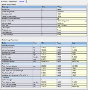
AxSTREAM can design single-stage, multi-stage and multi-module turbomachines with special machine-specific design features (see information in the blue box below) to ensure maximum flexibility as well as optimized calculation and post-processing times.
Solver, Data Input as Ranges and Design Space Explorer
The inverse solver allows the generation of large amounts of designs in a short span of time (up to dozens of thousands of geometries created per min) and is coupled to an optimizer to seek sets of parameters resulting in higher performances and ensures that the geometry selected for detailed design is already as optimized as it can be at the 1D level.
This is made possible due to the inputs being provided as ranges rather than fixed values, wherever desired. These ranges can then be analyzed in the Design Space Explorer tool to allow users to search for optimal values based on performance, size, manufacturability, etc.
In addition, filters can be applied to keep only geometries that fit user-defined criteria to eventually select the one design that provides the best compromise of performance vs size, for example. The design space can even be exported to a spreadsheet format for additional post-processing.
Moreover, Preliminary Design default settings allow getting as close to the final geometry as possible by including shrouds and seals information or clearance data, for example, at the earliest stage of the design process.
Add-On: Results Validation and Geometries Comparison at Design and Off-Design Conditions
AxSTREAM’s Preliminary Design modules also include a meanline direct solver which is enabled when the Meanline or Streamline license is available and allows validating the performances obtained for each geometry at design and off-design conditions. This makes it very convenient to compare performances across the entire range of operation (from surge / stall to choke, for example) as well as operation ranges themselves (surge margin comparison, for example). Note that in order to study off-design conditions the AxMAP license is required.
Preliminary Design for Redesign Tasks
The AxSTREAM Preliminary Design modules do not only allow creating geometries from scratch. Indeed, they can also be used to redesign or optimize some existing machines. This is done by setting appropriate parameters depending on the level of redesign/optimization desired and can range between maintaining the number of stages, axial and radial dimensions, blade heights, etc.
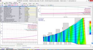
Whether the machine of interest was designed within the AxSTREAM platform or imported (through geometric data manual entry, ATLAS or AxSLICE) a necessary step to predict its performance is the 1D/2D Streamline Calculation module. Within a single interface users have the opportunity to run meanline (1D), streamline (2D) or throughflow calculations depending on the intended goal and the degree of accuracy vs computation time desired. Subsonic, transonic and supersonic flows can be calculated while accounting for real fluid properties.
While these different types of direct calculations are licensed individually and separately for each machine type, the unified interface makes it convenient by not having to learn multiple tools for similar capabilities.
Such calculations allow getting precise and rapid power, efficiency, pressure ratio of a turbomachine as well as distribution of kinematics and thermodynamics parameters in both streamwise and spanwise directions. Losses are also calculated and broken down so that designers can clearly identify where their machine is losing efficiency and therefore have some leads on how to improve it.
Leakages & Secondary Flows
Moreover, leakages are estimated based on seal geometry provided, extractions, injections, recirculations, and cooling flows. Leakages can be modeled as well and heat exchangers can be added to account for inter-stage cooling or heating.
Types of Solver
The meanline approach is a 1D calculation at the pitch (mean) line with extrapolation of the flow properties at hub and shroud.
The streamline approach is a 2D calculation accounting to real blade angles at each spanwise location for up to 49 radial stations and is especially useful for longer blades.
The throughflow calculation is a qualitative calculation that allows investigating flow structures for optimization, including presence of shocks, vortices, etc.
Scope of Work
The system can perform analysis of stages with full blade rows, with only a single rotor or stator, stages with counter-rotation, with or without cooling or secondary flows, and flow paths with axial and/or radial stages. Modifications on the flow path contours can be performed to impose additional size restrictions or increase endwall continuity.
Loss Models
The software includes some industry-approved loss models for profile losses, secondary losses, blockage losses, leakage losses, etc. while allowing users to customize or implement their own models and tweak the magnitude of each value for maximum flexibility and tool evaluation purposes.
Visualization & Post-Processing
Streamwise and spanwise graphical and tabular representations of parameters such as metal and flow angles, velocities, Mach number, losses and reaction are readily available for visualization as well as Mollier diagram and velocity triangles for any calculated spanwise sections. Additionally, mass balance diagrams can be reviewed to look at the leakages and secondary flows within the machine. Finally, contours of static and total quantities (pressure, temperature, enthalpy, velocity, Mach number, etc.) can be displayed on the turbomachine in both absolute and relative frames of reference.
Additional Capabilities
Numerical experiments can also be created to compare multiple runs in both tabular and graphical formats; different calculation methods, settings, number of spanwise sections used in the calculation, etc.
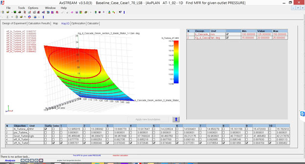
Moreover, these direct solvers are also used in the AxMAP & AxPLAN modules (require separate licenses) to perform sensitivity studies / off-design calculations and optimization using a Design of Experiment (DoE) approach, respectively.
AxMAP is AxSTREAM’s off-design performance calculation tool/feature which uses the meanline/streamline direct solvers to obtain accurate results of how a machine will operate under different circumstances. This includes information like at which mass flow rate values the turbomachine can experience stall, choke or surge or what rotation speed allows for optimum performance for a given set of boundary conditions.
Scope
About 50 parameters can be varied for each flow path component ranging from clearances to rotation speed, restagger angle, surface roughness or inlet/outlet boundary conditions so that the off-design performance of the considered machine can easily be evaluated in tabular form as well as on 2D and 3D maps.
Users provide a minimum and maximum value to use for each variable along with the number of values to use within the provided range. Moreover, the distribution of the values within the specific range can be adjusted to concentrate points in a region and variables can also take user-defined values for an enhanced flexibility.
Experimental data can be imported to compare with the simulations performed for one or multiple designs.
Results can be exported for additional post-processing, can be saved for later use within any AxSTREAM project as a template or can even be imported inside AxCYCLE to dynamically study thermodynamic cycles while accounting for off-design performance of the turbomachinery components.
While traditional optimization methods need a computation time that exponentially varies with the number of parameters involved there exists multiple design of experiment (DoE) approaches which allow significantly cutting this computation time. The best news about it is that the time saved using DoE grows with the number of variables selected (about 20 different parameters can be selected at once for optimization tasks).
Scope
A very extensive number of parameters can be chosen for their optimization based on any combination of criteria using individual, customized weights to define specific optimization tasks. This can all be done within the AxSTREAM platform while using the meanline and streamline solvers for direct task calculations.
A response surface is created based on a mathematical model that defines the characteristics of the given machine for the provided range of values and parameters. These allow performing very fast optimization tasks and provide the best 5 combinations of values for the selected components.
Results can be reviewed in tabular and graphical formats and files can be saved individually to reload an existing calculation or use it as a template for an upcoming task.
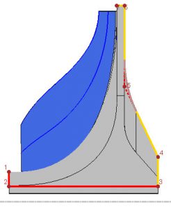
Whether the geometry comes from the AxSTREAM Preliminary Design tool or imported from a CAD model or cloud of points through the AxSLICE module blade profiling plays a crucial role in the performance of a machine both aerodynamically and structurally.
Both the Axial Profiler and Blade Design and the Radial Profiler and Blade Design of the AxSTREAM platform are presented in this page, respectively, and are licensed individually.
The Axial Profiler and Blade Design of the AxSTREAM platform enables users to design 3-D blades for rotating machinery such as axial turbines, axial compressors and axial fans through different profiling modes.
The AxSTREAM Radial Profiler and Blade Design allows users to easily design and edit rotor, stator and splitter blades for radial compressors, diagonal compressors and radial turbines.
Each blade can be profiled for each of up to 49 spanwise sections using different profiling modes to ensure maximum editing flexibility and guarantee performance. Profile properties for each section can be reviewed and edited to provide optimum designs for the given flow conditions stored in the AxSTREAM project database.
Once designed or edited blades geometry (axial only) can be stored to the ATLAS profile database and/or exported as X, Y coordinates. On the other hand any blade can be used in the other AxSTREAM modules like AxSTRESS or AxCFD for 3D analyses or exported to external software as CAD, FEA or CFD models.
Axial Blade Profiling Capabilities
Blades of axial machines can be pretty complex and can range in height from a few millimeters to more than one meter (~3 feet). Depending on the blade size, performance to achieve, manufacturing capabilities and cost different technologies can be used and are available in AxSTREAM; prismatic (cylindrical), twisted blades, lean (including bow), sweep, etc.
An interactive and user-friendly editing allied with a potential flow solver allows instantaneously reviewing flow parameter contours upon changes to the profile geometry to ensure optimum flow in the blades channel.
Furthermore, an optimization of profile for minimization of losses using user-defined ranges of geometric parameters can be set up to deepen the manual optimization performed.
Once each section has be successfully profiled these can then be stacked to fully define the blade geometry in 3D and allow for lean (direct and compound like bow lean for example) and sweep to be included for any stacking axis.
Axial Blade Profiling Post-Processing
To quantitatively and qualitatively evaluate the performance of a profiled 3D blade several options exist. These include the calculation of profile losses, representation of the blade loading, information about separation criteria, Mach number on the pressure and suction sides, etc. which can include results for different airfoils for comparison purposes.
On the mechanical side, estimations of blade stresses at different locations are available to reduce iterations between blade design and 3D structural calculations like in AxSTRESS.
A quasi-3D CFD (constant radius calculation) tool using viscosity and turbulence with customizable mesh allows calculating and displaying thermodynamic and kinematic properties contour as well as heat flux and velocity vectors in inter-blades channel. This Cascade CFD is very useful for transonic stages profiling, where the potential flow cannot predict all effects accurately.
Blade restaggering can also be performed to study how the throat area gets affected to allow for more or less flow rate. This restaggering can even be optimized based on the rotation speed using user-defined rotation schedules.
Profiling of the 3D blades is done through inlet and outlet geometric parameters, beta, theta and channel thickness distributions for each of up to 49 spanwise sections while providing interactive and automatic visualization of the changes on the blade geometry while recalculating the outlet flow angle.
Moreover, editing of the number of blades, blade metal angles, LE/TE angular offsets are possible with the possibility for blade lean and sweep.
Different profiling modes are available to ensure flexibility of the geometry editing for 3D blades, ruled-surface (for impellers) and prismatic (cylindrical) blade for vanes.
Radial Blade Post-Processing
The post-processing includes an interactive display of the blade curvature which ensures obtaining a smooth surface therefore helping prevent flow separation and minimize losses. Several options for leading and trailing edges exist: cut-off, circular or elliptical to fit the desired needs. Additionally, a polar view of each spanwise section of the blade allows users to review the blade profile and make desired changes.
Furthermore, blade restaggering can also be performed to study how the throat area gets affected to allow for more or less flow rate. This restaggering can even be optimized based on the rotation speed using user-defined rotation schedules.Restagger angle = 0 degree
Once the preliminary and detailed design of a turbomachine has been done it is good practice to check the performance and flow behavior using more accurate models before setting off to manufacturing and testing which are quite expensive; this is usually where CFD comes in.
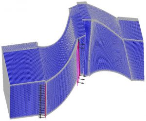
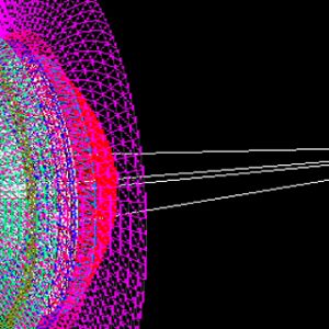
AxCFD allows running full 3D RANS computational fluid dynamics in turbomachinery channels for single rows, individual stages or full machine including elements like ducts, etc.
Pre-Processing
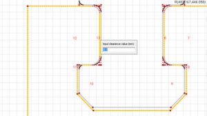
Thanks to the integrated architecture of the AxSTREAM platform geometries, boundary conditions, clearance values, number of blades, rotation speed, etc. are automatically inherited from the AxSTREAM project which significantly simplifies and reduces the pre-processing setup time while preventing human errors. These can however be edited as desired to study different effects. In a similar way periodicity conditions as well as inlet and outlet surfaces are automatically created based on the geometry from the AxSTREAM project.
An automated turbomachinery-specific, structured hexagonal meshing by customizable blocs is available for computational domain division. Different types of mesh generation are available and can be refined in each direction, in the boundary layer, in blocs, etc. and rotation zones. Location of cooling holes can be set up as well.
Solvers
Different problem formulations are available depending on whether the user desires to calculate a pressure value (inlet or outlet) or the machine mass flow rate. Viscosity and different turbulence models (including k-ε, k-ω, k-ε RNG, k-ω SST) can be used for new calculations or to resume existing ones. Heat transfer between the blades and the fluid can be accounted for along with the material surface roughness. Each computation can be run for a given spanwise location (radial section), for an axisymmetric sliceor for the entire 3D geometry.
Post-processing
Once the calculation is converged visualization of contours of pressure, temperature, velocity, Mach number, etc. is possible at any location within the channels through customizable post-processing spanwise and streamwise sections. Additionally, blade loading for any radial location can also be displayed.
Finally, export of CFD results allows comparisons at design and off-design conditions between different calculations using the same or different solvers (1D, 2D, 3D) as well as experimental results.
An inefficient blade that does not break is always more performant than an aerodynamically efficient blade that snapped in half. This is why once the aero design of a 3D blade has been performed its structural characteristics should be investigated.
AxSTRESS is an express structural, modal and harmonic analysis solver using a Finite Elements Method with a customizable, automatic turbomachinery-specific mesh generation. AxSTRESS also performs Campbell and interference (SAFE) diagram calculations as well as hot-to-cold and cold-to-hot calculations to consider the effect of blade untwist under operation.
Pre-Processing
Data is read from the AxSTREAM project database to define the blade geometry, aerodynamic loads and material properties as well as the rotation speed, number of blades, boundary conditions, etc. This allows for simplification of the pre-processing operations and prevents human errors.
Blade Attachments & Disk Design
AxSTRESS can be used to create blades with attachments and also blades as blisk. Different kinds of attachment templates for roots, shrouds, disks and lashing wires can be created and stored in the embedded attachment library and can be designed using interactive features.
Once in the library, they can be scaled and moved to adapt to different blades within the same or different stress projects. Legacy or standard attachments can also be imported into the attachment library and modified.
This allows significantly saving time when designing similar blade attachments. Additionally, AxSTRESS allows setting gap values between the blade root and the disk using a single click.
Furthermore, automatic conservation of attachments when reloading blade geometry allows a significant reduction of both iteration time and human error (no need to rebuild the attachments). AxSTRESS automatically determines the contact surfaces and model contact interaction between blade and disk by merging all nodes on the surfaces in all directions.
Meshing
AxSTRESS uses an in-house turbomachinery-specific mesh generator (mapped hexahedral for airfoils and triangular for attachments) which improves the mesh quality in the fillets depending on the mesh density for more accuracy results in the stress concentration places.
For airfoils, AxSTRESS generates at mapped mesh for more accurate results. Fillets can be created between blades and attachments (root and shroud) as uniform or variable between the leading edge and the trailing edge of the blade to reduce stress concentrations.
Analysis & Post-Processing
Additionally, for increased accuracy results of AxCFD computations can be used as aerodynamic loads for structural calculations and centrifugal, pressure and thermal loads can also be accounted for at design and off-design conditions.
The different types of analyses which can be performed in AxSTRESS are presented below:
Static analysis: Allows calculating the values of stresses and displacements in the different directions.
Modal analysis: Includes the calculation of a given number of natural frequencies of the system and their mode shape with the option to simulate several blades that are assembled in the same package together while accounting for pre-stress effect.
Harmonic calculation: Used to calculate the response of the system under a steady-state sinusoidal loading at a given frequency.
“Hot-to-cold” and “cold-to-hot” calculations: Determines the system’s geometry transformation between its “hot” state (running conditions) and its “cold” state (after manufacturing) that result from the blade untwist during rotation in a moving flow.
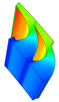
Campbell and interference (SAFE) diagrams: Illustrate the interference between natural frequencies and common exciting forces to locate potential (Campbell) and actual (interference using nodal diameters) rotation speeds that could prevent the safe operation of a turbomachine. Range of rotation speeds, number of modes and orders can be inputted by the user for the analysis.
Campbell diagramInterference diagram
Furthermore, AxSTRESS is equipped with excellent post-processing features including contours of displacement and stress in the direct directions as well as the option to extract stresses at custom-defined planes and sections.
Once a blade and its attachments have been finalized their geometry can be export to CAD models to obtain manufacturing drawings.
The AxSTREAM Software module, AxSLICE for reverse engineering allows turbomachinery services, OEMs, and overhaul businesses, to evaluate and analyze existing turbomachinery flow paths and develop new high efficiency designs for existing turbines, compressors and pumps.
This can be done through multiple ways of which the most convenient is through the AxSLICE module.
Geometry Recognition using AxSLICE
AxSLICE allows for importing and manipulating geometries from 3D CAD models or cloud of points to extract the profile characteristics of varying turbomachinery such as axial, diagonal and radial blades for use in the AxSTREAM platform for any number of spanwise sections.
Recognized geometries can be edited or adjusted directly inside the reverse engineering module.
The extracted characteristics of each profile (inlet, outlet and gauging angle, LE/TE radii, chord, etc.) can then be used in the AxSTREAM platform to run 1D, 2D and 3D calculations for design and off-design conditions, perform redesigns, reratings, optimizations, etc.
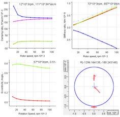
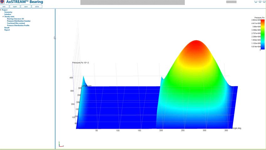
Rotor dynamics analysis would neither be complete nor reliable without accurate modeling of bearings. The AxSTREAM® Bearing module uses a finite difference method that allows calculating mechanical (including direct and cross-coupled stiffness and damping coefficients) and hydrodynamic (maximum fluid pressure, minimum film thickness, etc.) characteristics of the following:
Rolling elements bearing – Deep groove, self-aligning, spherical roller, straight roller, tapered roller, and so on
Bump gas bearing
Cylindrical journal (hydrodynamic) bearing
Fixed and tilting pad journal bearing
Fixed and tilting pad thrust bearings
The embedded library of fluids allows users to use new or existing incompressible and compressible fluids throughout different projects.
Analysis & Post-Processing
Several analyses can be performed in this module:
Steady state – Considers bearing state under loading in order to determine pressure distribution, bearing clearance, eccentricity, stiffness and damping.
Stability – Considers the bearing behavior during its transient operation and allows drawing conclusions on the stability of instability of the design for the studied rotation speed.
Map analysis – Performs several inverse analyses in order to calculate the evolution of the mechanical characteristics for a given series of rotation speeds.
These properties can then be exported to a printer-friendly report or the AxSTREAM® RotorDynamics software in order to automatically use the appropriate values during rotor dynamics analyses.
Additionally, pockets, misalignments, etc. can be considered for the different calculations.
Moreover, the lubricant flow rate is calculated along with the heat balance and temperature distributions.
Without proper rotor dynamics analysis, rotating machinery is at a higher risk of failure during operation. It is with this in mind that rotor dynamics software is arguably one of the most important tools in the turbomachinery design process.
The AxSTREAM RotorDynamics module is a software tool that can account for a number of things such as bearing characteristics, rotor imbalance and general excitation, critical speeds and whirl frequencies, and much more.
Applications
The AxSTREAM RotorDynamics software module has a number of different uses. This includes but is not limited to:
Jet engines
Cooling systems
Pumps
Compressors
Fans
Generators
Wind turbines
Steam turbines
Centrifugal compressors turbochargers
Gas turbines
Generators
Electric motors
Rotors and rotor trains are modeled as cylindrical or conical beam elements (plain or hollow) using a FEM (Finite Element Method) solver and mass-inertia elements can be used to simulate disks, roots, blades, impellers, probes, etc.
Scope of Analysis
Using AxSTREAM RotorDynamics, different types of rotating machinery analysis can be performed:
Static deflection analysis – Allows calculating deflection of the rotor under its own weight as well as reaction on each of the bearings in the system
Lateral critical speeds analysis for fixed and variable support stiffnesses
Unbalance response analysis
Whirl speed and stability analysis
Train torsional modal and transient analysis
Vibration analysis
Fluid film bearing analysis
Rotor balancing analysis
The program’s post-processing capabilities allow obtaining information about the rotor-bearing-support system like the following:
Static deflection form
Stresses, forces and moments throughout the machine
Critical speed mode shapes
Critical speed map
Rotor response plot
Amplification factor and separation margin based on provided unbalance and damping characteristics, as required by API standards
Stability plot and Campbell diagram for both lateral and torsional analysis
Torsion natural frequencies
Transient torsional responses torque and stresses
For more information on rotor dynamics, watch an introduction to our rotor dynamics training course.
An aerodynamically efficient and structurally sound blading is a must for any turbomachine. However, once the geometry of the blades and the attachment (root, disk, wheel, etc.) has been determined, the design work isn’t quite finished as attention must be brought to the design of the rotor itself. The rotor design iterative process should be conducted in parallel with the full scope of structural checks (such as centrifugal and thermal stresses, gravity sag, burst calculations, etc.) and rotor dynamics analyses. Each attached rotor component (blades, disks, interstage and end packing seals, journal and thrust bearings, etc.) have to be analyzed, properly designed and finally assembled on the shaft at appropriate locations. AxSTREAM RotorDesign software was created to be an integration platform between all design tools and calculation modules. Following design and analyses steps in AxSTREAM RotorDesign, the complete and highly reliable rotor with all attached equipment can be designed and exported in CAD for further steps of end product creation.
Process
The AxSTREAM Rotor Design tool allows users to import a new/existing/optimized flow path design from any AxSTREAM project in order to design the rotor based on AxSTREAM 2D flowpath layout or through a manual input of the blade axial and radial positions when used as a standalone software.
The corresponding AxSTREAM project contains information regarding the blades geometry, material, location, diameters, number, etc. Basing on this information, AxSTREAM Rotor Design calculates and prepares all required information for RotorDynamics and other modules involved in structural checks such as mass and inertia characteristics, loads and boundary conditions.
Flow Path Imported from AxSTREAM
The blades (with root and shroud attachments) and disk geometry can be imported from AxSTRESS – AxSTREAM’s 3D FEA tool – where they can be designed. The second option is to model them in a simplified manner within the Rotor Design module to create the correct rotor model in regards to the loads and equivalent mass-inertia and stiffness characteristics, providing additional constraints in terms of sizing of the rotor for its design.
Roots and Disks Geometry Import from AxSTRESS
Other component designs such as interstage and end packing sealing zones, couplings, journal and thrust bearing positions and appropriate shaft sections can also be added in the rotor assembly using the AxSTREAM Rotor Design libraries of standard components or created manually.
Once the initial rotor design is ready, the entire rotor model can be exported in the AxSTREAM RotorDynamics module to perform rotor dynamics analyses. If rotor dynamics and structural criteria are satisfied then CAD export can be performed to get rotor geometry to be used in further design steps. In other cases, the integrated Rotor Design system allows for a quick redesign of rotor components and recalculation of all steps in order to meet requirements.
AxCYCLE Software
In addition to AxSTREAM, SoftInWay provides AxCYCLE for thermodynamic simulation and heat balance calculations of heat production and energy conversion cycles. Capabilities and features include:
AxCYCLEallows users to quickly and easily design, analyze and optimize various thermodynamic cycles (thermodynamic simulation and heat balance calculations) in a user-friendly and flexible environment, from a restricted amount of known data.The tasks user can solve with AxCYCLE include:
Design new thermodynamic cycles from scratch
Analyze existing thermodynamic systems and their performance at design and off-design conditions
Redesign, optimize, rerate and upgrade existing plants
Troubleshoot and correct efficiency/reliability issues in existing hardware
Scope
AxCYCLE allows performing calculations on multiple types of cycles (Brayton, Rankine, etc.) and applications (with specific components) including:
Fossil Steam Power Plants
Nuclear Steam Power Plants
Cooled and Uncooled Gas Turbine Plants
Aerospace Gas Turbines Engines
Combined Cycles (gas-steam, gas-sCO2, etc.)
Cogeneration Cycles
sCO2 (supercritical carbon dioxide) Cycles
ORC (Organic Rankine Cycles)
Geothermal Cycles
Binary Cycles
Molten Salt Cycle
Waste Heat Recovery Cycles
Heat Pumps Cycles/Refrigeration Cycles
Etc.
AxCYCLE has several fluid libraries:
General Fluids – Includes steam/water, standard air, carbon dioxide, natural gas, etc.
COOLPROP – Contains over 45 fluid options (free database)
NIST REFPROP – Propane, ethanol, refrigerants, CO2 and more (required third-party application).
NIST Mixture – Contains several NIST mixtures
Combustion Products – Includes more than a dozen typical fuels combustion product
Thermal Oils – Contains therminol thermal oils which can be used for indirect waste heat recovery systems
Molten Salts – Contains several molten salts
Additionally, custom fluids, custom mixtures and custom combustion products can be used in cycles.
Cooling flows and secondary flows can be thermodynamically analyzed using AxCYCLE by modeling the complete gas turbine with turbine, compressor, combustion chamber, extractions, injections, etc. while automatically recalculating the fluid properties at each component’s inlet and outlet.
Cycle Creation Process
Starting from the selection of components using drag-and-drop from respective libraries (turbomachine, heat exchange, engine, library of gas turbine engines, library of internal combustion engines, burner, separation, mixing, valve, seal, generator/motor, etc.), users progress with the cycle assembly as desired to model an infinite number of different systems.
After the cycle assembly the engineer needs to specify the data necessary to run calculations.
As a conceptual 0D tool, AxCYCLE uses only the basic thermodynamic parameters of the components such as pressure, enthalpy, temperature, fluid quality and basic performance parameters such as efficiency and pressure loss.
No mechanical or geometric data is required which makes it extremely convenient and adapted to investigate concepts when the components of the system have no defined characteristics as well as to study existing systems where some geometric/mechanical data may be unknown.
Each parameter in AxCYCLE can be either inputted or calculated. This allows for an enhanced flexibility of problem formulation to, for example, calculate mass flow rate or heater outlet temperature based on given boundary conditions and power requirement or specify the flow rate and boundary conditions to obtain power.
Additionally, multiple options are available for different components to be modeled in specific ways; for example heat exchangers can be characterized by their efficiency or pinch point, turbines can be conceptual or behave as per existing hardware, etc.
For steam cycles the embedded Steam Cycle Wizard tool allows simplifying the components selection, cycle assembly, property type specification and boundary conditions input through an easy-to-use interface.
Analysis & Post-Processing
Thermodynamic cycles can be analyzed at their design point or at off-design conditions to calculate power production, heat and fuel consumption, rejected heat, thrust, thermal efficiency, etc.
Embedded P-H and T-S diagrams allow reviewing the thermodynamic process of the current system and also allow superimposing the characteristics of other cycles as a mean of comparison.
Printer-friendly simulation results (reports) can be automatically generated.
AxCYCLE systems and their components can be exported to the AxCYCLE Economics module to evaluate the capital costs, payback period, levelized cost of electricity, influence of renovations on ROI, etc.
AxCYCLE can also be linked to the AxSTREAM platform to:
Extract boundary conditions for turbine, compressor and pump conceptual design
Import turbomachine performance maps to study cycle at design and off-design conditions using actual efficiency values.
Cycle Off-Design Calculations, Parametric Studies and Optimizations
In addition to design point calculations AxCYCLE includes several tools for system off-design calculation, parametric study and optimization tasks.
AxCYCLE MAP
MAP is a multi-run tool used to run a series of calculations for one or two variables. AxCYCLE MAP is a very effective tool to study the influence of operational parameters on cycle performance. It is the ultimate tool to calculate cycle performance curves as it can automatically take into account components off-design efficiency based on the boundary conditions inputted or calculated; these include for example the dependency of efficiency on turbomachinery components rotation speed and pressure ratio, the influence of component aging, or can be used to study the effects of variations of operating conditions and component parameters on cycle performance.
AxCYCLE PLAN
AxCYCLE is fully capable of thermodynamic cycles optimization calculations including through the use of a DOE approach (Design Of Experiment) in the PLAN tool. This multivariable tool can be run for any combination of input and output parameters within dozens available (up to 20 variables can be selected at once). The DOE engine itself selects values within the provided range, in an optimized way, to minimize the number of solver runs required to optimize a cycle. The obtained results are used to build “response surfaces” that are used as abstract models for optimization.
AxCYCLE QUEST
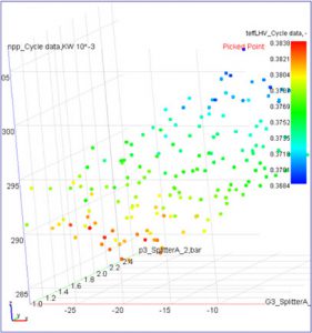
The QUEST tool inside AxCYCLE is a quasi-random search algorithm which can be used to optimize combinations of parameters within a given range, for as many design variables as desired and for any given number of combinations of parameters. Results are plotted on a 3D design space which allows easily reviewing the best combination of values for a given task while allowing users to set filters to customize and refine the optimization task.
AxCYCLE CASE
To study several cycle load points the AxCYCLE CASE tool is generally used. It allows users to specify the desired value for each of any number of variables to select in order to analyze how the system would behave under different conditions. For enhanced user experience AxCYCLE CASE is fitted with an option to interface to and from spreadsheets containing results and/or values for the different parameters selected. Some examples of CASE tasks include studying the performance of the given cycle upon opening or closing of valves, analyzing the required boundary conditions to obtain a given take-off vs cruise thrust for an aerospace gas turbine or hourly energy demand of a power plant.
AxCYCLE Economics allows users to quickly and easily estimate and compare the cost of one or many projects and configurations to determine the viability of a thermodynamic system throughout their life cycle. Coupling with the AxCYCLE thermodynamic solver not only allows searching for cheaper projects, but also techno-economically optimizing the project as trade-offs between thermal performance (power, efficiency, heat rate, etc.) and system complexity/cost are examined closely without requiring detailed information about the different components (no mechanical or geometric data required).
The absence of detailed design data permits accurate calculations as to whether a project is at the conceptual/feasibility stage or already existing.
Some tasks users can solve using AxCYCLE Economics for new facilities include:
Capital cost estimation
Selection of power generation technology and process scheme
Fuel type selection
Comparison of different scenarios/projects
Economic analysis throughout lifecycle
For existing facilities the scope of work in AxCYCLE Economics includes:
Capital cost estimation
Economic assessment of enlargement or renovation
Comparison of different scenarios/projects
Economic analysis throughout lifecycle
Scope
AxCYCLE Economics allows performing classes I-III economic analyses of power and heat generating units throughout its life cycle. These analyses are sufficiently reliable to get budget approval and can be used to perform scenario and configuration quantitative and qualitative studies.
Calculations of purchased equipment cost, TCI (Total Capital Investment), NPV (Net Present Value), payback period, LCOE (Levelized Cost Of Electricity), etc. can be performed. Results are presented in tabular and graphic formats (including drawing of financial charts) with export to spreadsheets as CSV files.
Similarly, annual economic indices can be outputted such as plant performance evolution, prices, revenues vs expenses, payments, cash flows, etc. for any number of projects.
Simulation Process
Thermodynamic systems calculated in AxCYCLE for performance can be exported to an AxCYCLE Economics file that will automatically read the main components present – HRSG (heat recovery steam generators), feedwater heaters, condensers, pumps, turbines, chillers, fans, etc. – as well as their boundary conditions and characteristics. This information allows calculating the individual cost of each component as well as their auxiliary equipment using embedded (internal library of models for main equipment is provided) or customized cost estimation models or even by directly inputting the exact cost if known.
The total purchased equipment cost (PEC), total delivery equipment cost (DEC), total capital cost investment (TCI) and specific capital cost (SCC) are also calculated at this step for any fuel, combination of models and inputted cost values and inclusion of spare parts.
Results
Cost of Auxiliary Equipment:
98,968,166.2 USD
Total Purchase Equipment Cost (PEC):
346,388,581.8 USD
Total Delivered Equipment Cost (DEC):
381,027,440.0 USD
Total Capital Investment (TCI):
1,149,178,759.0 USD
Specific Capital Cost (SCC):
2,967.2 USD/kW
Once component costs have been determined using embedded or customized cost estimation models, cash flows can be computed after inputting data regarding the evolution of system performance, operations & maintenance costs, financial & economic assumptions (debt vs equity), escalation rates and so on. At this stage, renovations can also be included in the model to account for an improvement of performance associated with a given cost and downtime to study the advantage of overhauls on performance and finance while optimizing the number and position in time of each operation.
Cash flows are then calculated and provided as tabular and graphic formats with the option to export the results to a third-party program.
Additionally, a summary provides essential information about the project while a much more thorough report features detailed data throughout the lifetime of the system to provide to clients, investors, and so on, or, simply for additional post-processing.
Economics Project Comparison
Total Capital Investment (TCI) is the total cost needed to initially build the facility and bring it to a commercially operable status, which will be depreciated over time. It includes:
Civil/structural costs
Mechanical equipment supply and installation
Electrical, instrumentation and controls supply and installation
Project indirect costs, fees and contingencies.
Owner’s costs
Through this index and many others (such as payback period or specific capital cost), AxCYCLE Economics allows the operator to easily compare several alternative projects with different sets of equipment, power generation technologies and/or fuels.
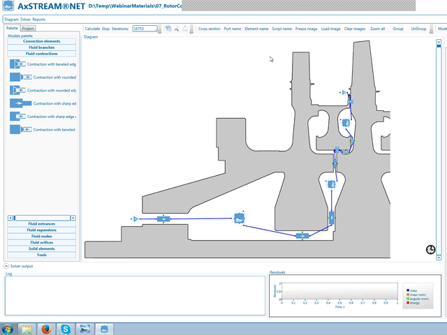
AxSTREAM NET Software
In the early phase of a thermal-fluid system design process, the geometry has yet to be defined (complete 3D solid model of the flow path geometry is not available). In this design phase a flexible method of varying the geometry and elements of the thermal-fluid system is very useful for estimation of leakage, cooling or bleed air flow parameters for different fluid path sections while taking into account heat exchange of cooling flow with metal surfaces.
Some Examples of Applications:
Gas turbine secondary air systems
Gas turbine blade cooling systems
Steam turbine secondary flow systems (including gland seal leakages)
Industrial gas systems
Ventilation systems
Other thermal-fluid systems
Solver
AxSTREAM® NET is 1D system modeling solver based on finite volume method that uses a thermal-fluid network approach to simulate secondary flows and heat transfer at steady and unsteady (transient) conditions. The non-necessity for 3D geometry allows for its use before finalizing the blades geometry while keeping a good accuracy in the results in a very short computation time. This helps considerably reduce the iterations time required to optimize aerodynamic cooling losses and machine performances.
Scope of Work
This flexible tool allows creating an infinite number of systems and sub-systems of solid structures, convection components and fluid path elements through drag and drop from library of embedded components and possibility for users to incorporate their own elements and formulations.
Individual flow path components and full flow path (for example, turbine and compressor) can be modeled. For each fluid path section (represented by the appropriate element(s)), the program calculates fluid flow parameters for inlet and outlet cross-sections, like velocity, pressure, density, temperature, mass flow rate, total parameters, as well as pressure loss, convection, conduction, heat transfer coefficient, etc.
System Components
Element libraries include not only basic components like pipes, ducts, walls/bodies and orifices but also special components (labyrinth seals, rotor-stator cavities, rotating annular gaps and others) to model complex turbine secondary flow systems, including different convection formulations. The computations also take into account rotations, changing cross section areas of ducts, flow bends, air heating, and other features.
Fluids:
Integration of NIST RefProp fluids
Customized mixtures
Applicable to compressible and incompressible fluids
Automation
For enhanced flexibility and automation extensive scripting capabilities (C# language) exist in AxSTREAM® to calculate properties based on user-defined subroutines.


 Depending on the license(s) available, machines that can be created using the Preliminary Design modules of AxSTREAM include:
 The inverse solver allows the generation of large amounts of designs in a short span of time (up to dozens of thousands of geometries created per min) and is coupled to an optimizer to seek sets of parameters resulting in higher performances and ensures that the geometry selected for detailed design is already as optimized as it can be at the 1D level.
 AxSTREAM’s Preliminary Design modules also include a meanline direct solver which is enabled when the Meanline or Streamline license is available and allows validating the performances obtained for each geometry at design and off-design conditions. This makes it very convenient to compare performances across the entire range of operation (from surge / stall to choke, for example) as well as operation ranges themselves (surge margin comparison, for example). Note that in order to study off-design conditions the AxMAP license is required.


 Restagger angle = 0 degree