As power systems evolve, the need for accurate, intuitive simulation tools becomes more and more important. With PSCAD/EMTDC you can build, simulate, and model your systems with ease, providing limitless possibilities in power system simulation. Included is a comprehensive library of system models ranging from simple passive elements and control functions, to electric machines and other complex devices.
PSCAD has benefited from over 40 years of continuous research and development. We are inspired by the ideas and feedback from our global user base. This philosophy has helped establish PSCAD as the most popular power system transient simulation package available today.
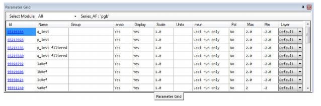
The component parameter grid pane provides a convenient means to display the parameters for all instances of a given component or module definition. More importantly, it enables the ability to modify multiple parameter values in multiple component instances simultaneously.
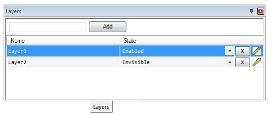
The layers pane is the interface to the schematic canvas drawing layers feature. Drawing layers provide the ability to efficiently enable or disable components on the canvas, or to toggle the visibility of any objects that appear on the canvas.
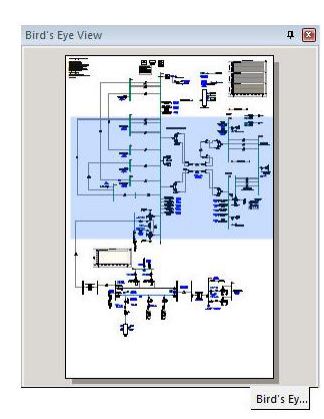
The Bird’s Eye View navigation pane provides an overview of the entire Schematic or Graphic canvas and indicates what is currently in view with a blue box. This tool is an important part of the collection of navigational tools in PSCAD, and is used to easily zoom and navigate. This pane is particularly helpful when working with very large projects.
Volley launch provides the ability to launch multiple EMTDC simulation runs in parallel (up to a maximum of 64), based on a single PSCAD case project. To set up a volley, a simulation must first be added to a simulation set. Once added, simply invoke the Simulation Options dialog and adjust the Volley Count option. For example, if you want to launch 7 simultaneous runs of a single project, then set the Volley Count to 7. When you next launch the simulation set, 7 instances of that simulation will be launched in parallel, utilizing all available processor cores.
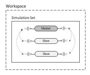
The Root Control Interface (RCI) was first released as part of the PSCAD v4.5 minor upgrade. Root control allows for one root, or master project, to control multiple slave projects, where both master and slaves must be part of the same Simulation Set. The idea behind the development of the RCI was to support both parameter sweep, as well as optimization-based, multiple-run studies. Like the simulation sets, the RCI is an inherent part of the workspace, which enables interproject communication within a single simulation set. This is accomplished using the already well defined Radio Link transmitter and receiver components, which were extended in v4.5 to include a provision field for a foreign namespace. This instructs the link to collect its value from a foreign source, and thus allows for a more sophisticated means of multiple run control.
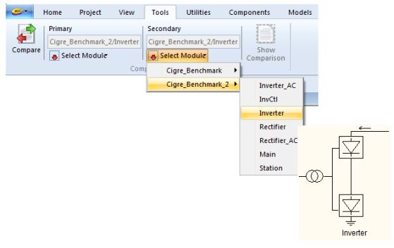
The schematic comparator tool allows for quick and convenient visual differentiation between module component definitions. By selecting two sources for comparison (from the Tools tab in the ribbon bar), users can click the compare button to perform a comparison of the two definitions.
The user will be presented with a visual display of the differences between the two modules. A results table will give users a text description of the differences, along with the values that were found to be different. Additionally, components with differences will be surrounded in color coded highlighting boxes on the schematic canvas of the primary source.
Official support has been added for the Intel® Visual Fortran Compiler for Windows (Versions 14 & 15).
The free Fortran compiler supplied with PSCAD has been upgraded from v4.2.1 to v4.6.2. This upgrade also resolves multiple bugs that were inherent to the older GFortran version.
Projects or workspaces may now be loaded into the environment via drag and drop. Simply select a project or workspace file (from say Windows File Explorer) and drag it over the workspace window. Release the mouse button and the file will load.
The blackbox algorithm now supports the black-boxing of entire module hierarchies. The same rules still apply as when black-boxing a single module (i.e. no output channels, runtime components, etc.). Blackbox collects all unique module definitions and generates both a source file (*.f) and a compiled object file (*.obj) for each. It also goes one step further and binds all object files into a single static library (*.lib) file.
It is now possible to show both project and workspace files directly in their respective folders. Simply right-click on either a loaded project or the workspace and select Show in Folder.
Users may now pan the schematic canvas horizontally by holding down the Shift key and rolling the mouse wheel
When working with large simulations and multiple run scenarios, errors can be time consuming and costly. In the past we have been asked for the capability to execute a ‘dry’ simulation whereby the user can quickly check to make sure the configuration of each run is valid. Unfortunately, there was no way to run only a partial and then skip to the next run in the sequence.
A new button, called ‘Skip’, has been added to the ribbon, which sends a message to EMTDC instructing it to jump to the end of the run and begin the next one. In the case of simulation sets and master/slave batch configurations (including volley), the entire coordinated run will skip to the next iteration.
While we always strive to run faster and larger simulations, sometime it is the ‘small ones’ that matter. This is especially true when trying to demonstrate or study an event that occurs in a very short period of time. If the simulation is small, the plotting can fly by in just the blink of an eye, making it hard to experience the event as it occurs.
What is required to actually slow down the plotting is a kind of ‘slow-motion’ effect, similar to manually decreasing the time step. This has been accomplished using to slow control and slow factor slide control.
For presentation and teaching purposes, the user can now control how quickly the event is performed. A toggle button turns the slow mechanism on and off, while the slide control provides plotting delay of 1 ms up to a maximum of 10 ms.
In order to maintain compatibility with messages sourced from Fortran compilers, the font for the message table has been changed to a mono-spaced font. This will help with groups of messages that rely on a mono-spaced layout in order to make any sense.
Local complex variables may now be declared in component definition script.
Progress bars have been added to both the workspace project and the simulation trees. When running a standalone project, a project bar will appear directly behind the project name (if enabled) to indicate its runtime completion percentage. This option is disabled by default and may be enabled by adjusting the Show quick run progress bar option in the Workspace category of the Application Options dialog.
If running a root control simulation (i.e. master/slave configuration), progress bars will appear in the over the simulation tasks in the simulations tree.
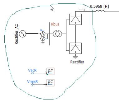
Two new selection tools have been added to the ribbon control bar: The Freehand and Point selectors.
The freehand selector allows you to encompass a group of components in a freehand circle, similar to a ‘lasso’.
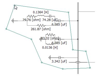
The other is a Point selector, where the components are encompassed with a polygon, or collection of points.
A new feature has been added to help consolidate and organize workspaces. Workspace can sometimes become unruly, containing several projects which may have links to additional source or binary files. Both the project and dependent files can be scattered throughout local folders, making it very cumbersome to transfer the workspace from one computer to another. The workspace consolidator alleviates this issue by allowing the user to consolidate, organize and reset all dependent file paths with a click of the mouse.
The consolidator moves all projects into an organized folder structure that looks similar to the following.
A new 64-bit build version of EMTDC is now included with PSCAD. It is important to note that 64-bit EMTDC can only be used along with the Intel® Visual Fortran Compiler for Windows version 15 of greater, as well as the 64-bit version of PSCAD.
PSCAD will now maintain a backup file for both the workspace and all loaded projects. This recovery file is updated every 30 seconds and is deleted upon exit of the application. In the event that the application crashes, the backup files will be detected on restart and the user will be asked if he or she would like to recover the backups.
The Maximum/Minimum Array Value and Location component allows the circuit designer to find the value and location of a minimum or a maximum element value in an array signal.
This component is meant to be used for the dot product of 2 arrays. For example, you can use the dot product of 3-phase voltages and currents to measure the instantaneous power.
This component generates a surge waveform, typically used in lightning studies, and compliant with IEEE, IEC or CIGRÉ standards.
This updated component allows configurable generator and exciter positions. The previous component dictated that the generator and exciter had to be positioned at the end of the rotating mass.
MyCentre is a cloud-based tool designed specifically for you. It provides you with a centralized place to find news, product announcements, software, and of course world class support. Training videos, reference material, and updates are all now available through MyCentre.
This is only the beginning, in the near future, you will be able to personalize MyCentre, as well as use it as a community or social networking tool. We want to foster intra-industry collaboration. We want you to be able to communicate with others, and share a variety of information, such as models, libraries, technical papers, solutions, and expertise.
The PSCAD Support Desk often requires log files for debugging client installation, licensing, and simulation problems. New enhancements to the Support Request Form (inside PSCAD) include automatic collection and attachment of setup and project files. The user has the ability to include these files and attach additional files such as images of errors or documents.
The PSCAD 64-bit product is identical to its 32-bit version counterpart, except that it is compiled as a 64-bit application. It directly addresses the ‘Out of memory’ issue that some power users have experienced when attempting to run very large simulations: If a simulation exceeds the allocated process memory of 2 GB (imposed by the Windows 32-bit operating system) then the simulation will crash, resulting in lost time. It is important to note that although a 64-bit application will open up an enormous memory space (4 TB or 4,000 GB) the speed of execution is not affected. That being said, any machine that may be constrained by memory limits may see a big speed improvement with the added room: Speed improvements are tied to the memory loading, rather than the memory capacity.
It is now possible to simultaneously launch and run multiple EMTDC™ simulations. Both sequential and parallel simulation runs are possible by defining what are referred to as ‘simulation sets’ in the workspace.
Projects loaded under the Projects branch in the workspace may be added as a Simulation to a Simulation Set. All simulations in a particular set will be launched simultaneously, utilizing all processor resources available. Each set is run sequentially: In other words, set 1 will run all projects that are defined in it then set 2 will run and so on.
Control for multi-EMTDC can be found in both the Simulations right-click pop-up menus, as well as on the Run button in the ribbon.
The search feature introduced with PSCAD v4.4 has been redesigned based on user feedback. It has been reformed to use less real estate, and was simplified for ease of use. New functionalities include enhanced scoping (users may search based on project or specific module), as well as ‘Match case’ and ‘Match whole word’ options. Also, both ‘Node Number’ and ‘Brand Number’ search functionality has been added to the same interface.
Black-boxing allows users to design their control system schematically, and then quickly collapse it into a pre-compiled, binary version of itself, thereby protecting any intellectual property invested in the design, before distributing the model to clients. The black-box algorithm performs the following functions automatically:
FORTRAN Source Generation: PSCAD already generates FORTRAN source, however this code is written specifically to interact with EMTDC as part of the greater simulation project; and is not formatted to be used as external source. The black box function will generate FORTRAN source code specifically formatted to be used as external source for inclusion in any EMTDC simulation.
Automatic Object/Library file Creation: The option to compile the generated source file into an object file is provided.
Automatic Component Creation: A new, non-module component definition and instance is created, based on the contents of the module schematic canvas. This includes ports, parameters, graphics and script segments.
In past versions, the workspace and the application itself were inextricably linked together as one compete unit. Now, the application and the workspace have been divided into separate entities. What this means from the user’s perspective is that entire workspaces may be loaded, saved and unloaded without having to close the application. A single workspace may house multiple projects, including both libraries and cases, as well as possessing its own unique setting options.
Module components no longer require their definitions to reside in the local project: Entire module hierarchies can be stored in a library project and instantiated for use in multiple case projects. When a project containing module instances sourced from another project is compiled, the definition information is extracted from the external project and utilized in the same manner as if the module definitions were stored locally.
The Photovoltaic (PV) Source component is assumed to consist of several strings of PV modules, connected in parallel; where each string could consist of a number of PV modules connected in series. All PV modules in the array are assumed identical. A higher rating can be achieved by simply stacking the sources. The Maximum Power Point Tracker component is used to track the maximum power point (MPP) voltage of the photovoltaic.
The Search Results table has been designed to display all results in tabular format. Even objects such as curves in side graphs are displayed as results in the new table. The search results are navigable; they will bring you to the exact location of where that result source is in your project. This can be done by simply double-clicking the specific table row, representing the search result. The table also allows the user to re-organize search results by any of the table columns.
It is now possible to combine both underground and aerial cables in the same right-of-way! This feature affects mainly the ground plane component, where you must specify the formulae used for aerial, underground and mutual (underground/aerial) earth return representation. You must also specify in the coax or pipe cable components, whether or not they are aerial or underground. Note that it possible to define the above-ground cables as bare, which is equivalent to an overhead line conductor. In other words, you can now effectively simulate overhead lines and underground cables within the same system. In the future, support will be added to allow actual tower components to be used to define the aerial cables.
Introduction to FACE Software
This webinar will provide you with an indepth introduction to FACE Software.
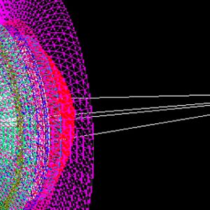
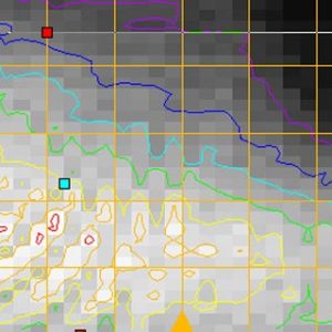
New Product – FACE Software!
This video will provide you with a general overview of FACE Software – Field and Corona Effects.
Lightning Over Voltage Simulations in PSCAD™ EMTDC™
This webinar provides information on Lightning Overvoltage Studies using PSCAD/EMTDC.
Webinar on Transient Recovery Voltage (TRV)
This webinar will show you how to do TRV simulations in PSCAD/EMTDC.
Webinar on Parallel Simulation using Concurrent EMTDC
This webinar will provide you with an overview on large system parallel simulation using concurrent EMTDC.
Module Comparison Tool
This video will show you how to setup the module comparison tool and how to use the tool to find differences between modules.
Consolidate your workspace in PSCAD
In this video you will learn how to use the ‘Consolidate Workspace’ feature.
How to copy a custom component using PSCAD
This video will show you how to copy a custom component from one space to another.
Birds Eye View in PSCAD
This video will allow you to visualize and navigate large systems in PSCAD.
How to use the Blackbox Hierarchy feature in PSCAD
PSCAD now supports automatic blackboxing of control systems that are organized in the hierarchy.
Copying and pasting components and definitions between PSCAD
In this video you will learn how to copy and paste components and definitions between PSCAD.
Copy Transfer feature using PSCAD
The Copy Transfer feature allows you to copy a definition and its child definitions from one project to another.
The ‘Drag Drop’ feature using PSCAD
This video will show you how to load projects into PSCAD by simply dragging PSCAD files from a windows folder.
Export definitions that contain other page modules using PSCAD
Learn how to export definitions that contain other page modules.
Free Hand Selector feature in PSCAD
The free hand selector allows you to work around complicated circuit topologies.
Multiple Run Skip in PSCAD
Learn how to skip individual simulations of a multiple run.
Runtime Progress Bar
Display the progress of your simulations in PSCAD.
Runtime Slow Motion feature
Slow down your simulations in PSCAD.
Sticky Note feature
Allows you to edit the text directly in PSCAD
Stop Simulation Set feature in PSCAD
Allows you to stop any project that is running a simulation set.
ENI Tutorial
This video will cover the following topics:
-Introduction to the Electrical Network Interface (ENI)
-Introduction to the Control Signal Carrier (CSC)
-How to use the ENI and CSE to speed up simulation
Layers feature in PSCAD
This video will discuss the the layers feature in PSCAD and how to set up layers.
Parameter Grid feature in PSCAD
What is the Parameter Grid pane and how to use it.
New Features of PSCAD v4.6
PSCAD 4.6 is coming soon! On October 2nd, PSCAD users tuned into a webinar that previewed the newest minor update to the X4 product! Watch the webinar to learn helpful tips and to gain hands-on experience.
How to get the Free Edition
This video demonstrates how to download, install, and activate the Free edition.
An introduction to MyCentre
This video provides a simple overview of MyCentre.
How to use the support request
This video provides a brief overview of the new support request form and how to use it.
The workspace
This video provides an overview of the PSCAD workspace.
Simulation sets and batch run
This video demonstrates how to manage multiple simulations using sets.
How to blackbox modules
This video demonstrates how to blackbox a page module into an equivalent, non-module component, complete with generated source files and compiled binary files.