PC-DMIS 2017 R2 cracked software
$ 120.00
PC-DMIS 2017 R2 is the latest release of Hexagon Manufacturing Intelligence’s world-leading dimensional measurement software package for coordinate measuring machines (CMMs).
PC-DMIS 2017 R2 continues the measurable trends towards great product stability and improved user experience. This release marks another significant step forward, with even more valuable enhancements that contribute to overall workflow improvements across all areas of the product.
PC-DMIS leads the way in revolutionising measurement, pioneering technologies such as:
- Use of CAD models in the inspection process
- Directly linking CAD systems and measurement software through its Direct CAD Interface (DCI) technology
- Implementing a full set of sheet metal measurement routines tailored for the automotive industry
- Digitally simulating measurement in an offline virtual CMM environment
- Easily aligning complex contoured parts using breakthrough iterative alignment technology
PC-DMIS is standard equipment on all Hexagon Manufacturing Intelligence measurement devices and is also available as a retrofit package for most other measurement equipment manufacturers, allowing users of non-Hexagon equipment to take advantage of PC-DMIS technology.
PC-DMIS comes in three basic configurations, Pro, CAD and CAD++, with optional modules available to fine-tune for specific needs. It is also available in an offline version for virtual programming.
Description
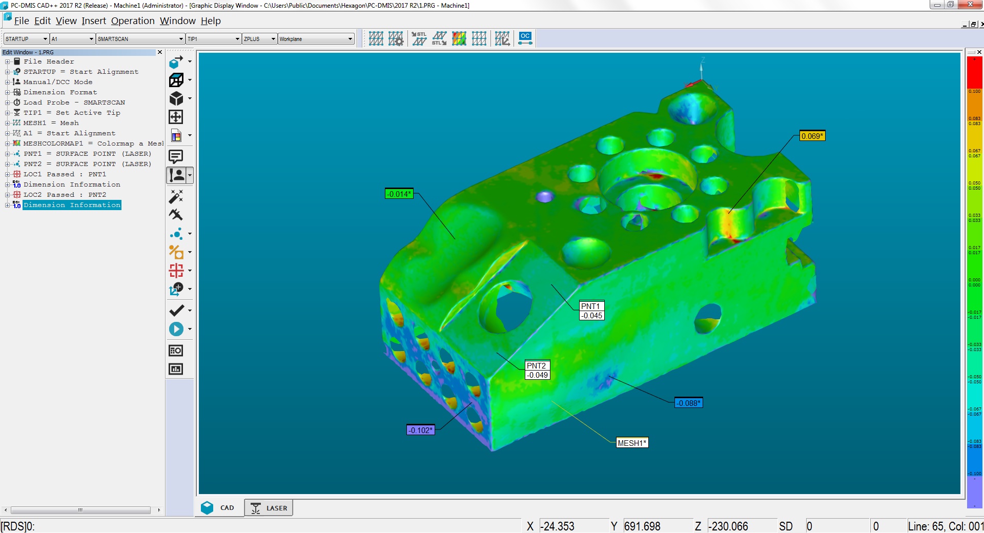
New updates improve the native mesh resolution from import to visualisation. PC-DMIS 2017 R2 makes it easy to apply a colour map to the mesh data object and create annotation points, align mesh data objects to the CAD model or align a mesh to another mesh object, and now you can create one Surface Colour Map, group the selected surfaces, and assign different tolerances to each group.

We’ve improved the native mesh resolution from import to visualization. You can now also create one Surface Colormap, group the selected surfaces, and assign different tolerances to each group. When a colormap contains multiple groups with different tolerances, the color scale is automatically shown using percentages. When you create a Surface Profile Dimension that uses a colormap with grouped, multiple tolerances, you can expand the COPFCOLORMAP feature to show the individual groups. You can create a Surface Profile Dimension for each COPFCOLORMAP group.
Other Mesh Improvements:
- You can apply a colormap to the mesh data object and create annotation points. The mesh is compared to the CAD model and then the mesh colormap is applied to show the deviations.
- To support data from other interfaces, PC-DMIS can use a mesh as a data object. Mesh functions are located on the Mesh toolbar (View | Toolbars | Mesh). These functions require the optional Mesh license, which is available only with an LMS license.
- You can align the mesh data object to a CAD model or align a mesh to another mesh object. If you align a Mesh data object to a CAD model, you can use either the Auto Compute or Point Pairs/Refine Alignment method. If you align a mesh to another mesh data object, you should use the Point Pairs/Refine Alignment method. The Auto Compute method is not available for mesh-to-mesh alignments.
- If you select the Empty Mesh button on the Mesh toolbar, the current mesh object empties. This is typically done to prepare to import a new mesh object. You can also insert an Empty mesh command into the measurement routine through the mesh Operator function.
The Caliper Tool has also been improved:
- You can set the sizes of the Caliper start and end tips individually. The
- Gage dialog box contains separate options for the start and end tip sizes. You can also change a tip size from the Edit window.
- You can use the Caliper line thickness option on the OpenGL tab in the CAD and Graphic Setup dialog box to set the thickness of the Caliper line.
- When you create a Caliper gage, PC-DMIS automatically calculates the start, mid, and end points. These points automatically appear as valid selections in the Dimension, Construction, and Alignment windows.
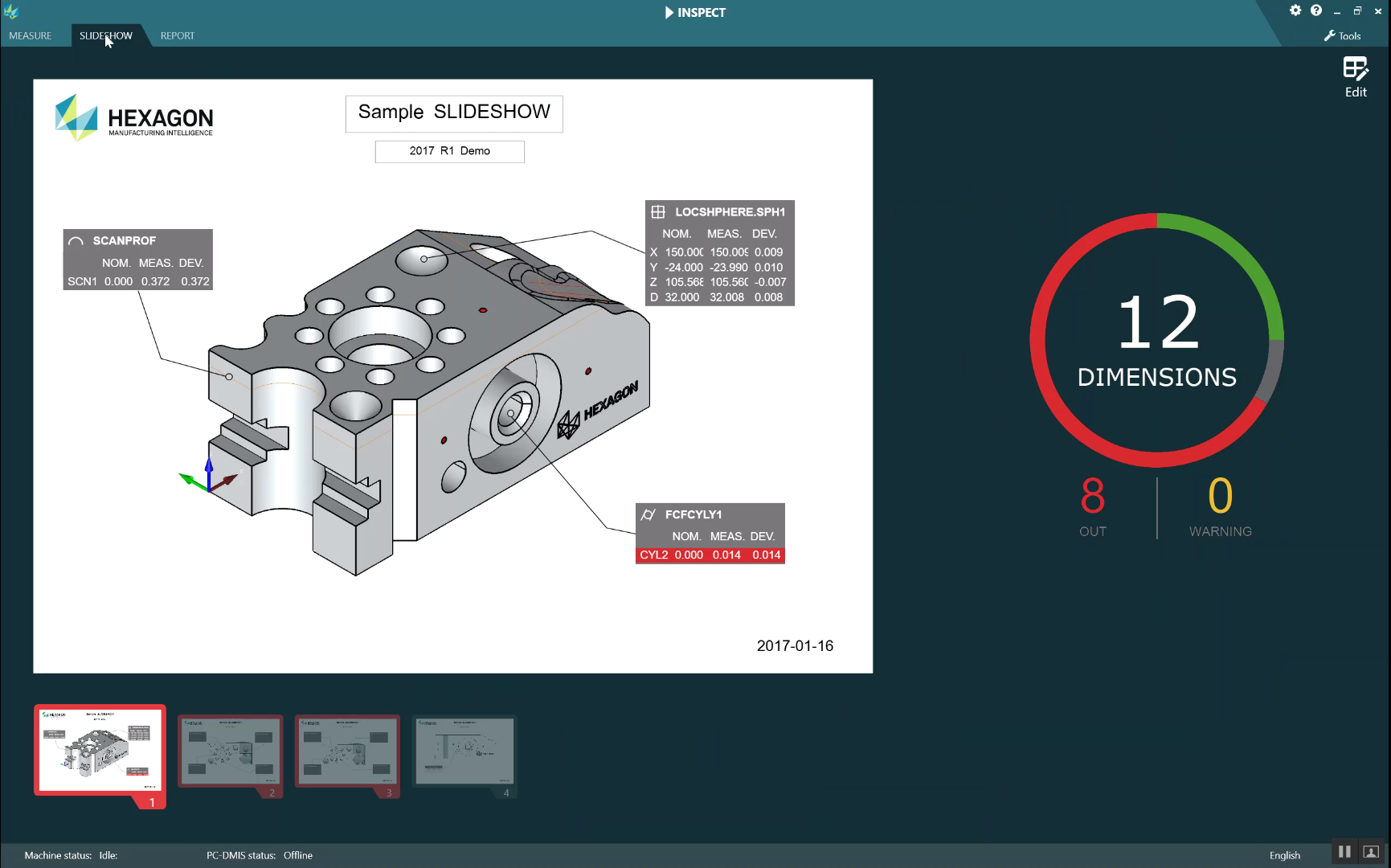
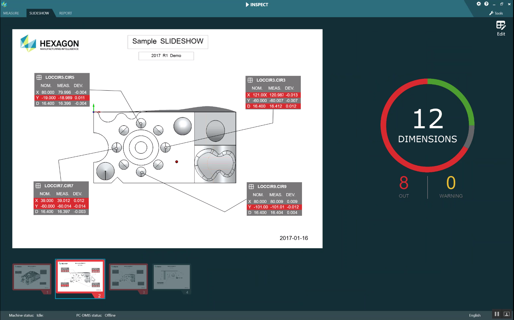
Create unlimited customisable layouts with inspection results populated during measurement and view your inspection in a whole new way! The optional Slideshow tab (additional licence required), can display multiple slides of dimensional and informational labels whenever you execute a measurement routine. With Slideshow, you can create or edit a template that contains the label controls on the slides to report the measured dimension data.
The optional SLIDESHOW tab (additional license required), can display multiple slides of dimensional and informational labels whenever you execute a measurement routine. With SLIDESHOW, you can create or edit a template that contains the label controls on the slides to report the measured dimension data.
Suppose, you have 100 dimensions in your measurement routine and you want to provide real-time feedback for the ten-most critical dimensions. In your template, you can select those ten dimensions and then place them in slides (template pages).
During execution in INSPECT: When you start the execution of a measurement routine, the labels on the slides contain the dimensions that are specified in the template file.
Initially, these labels don’t have any measured data. As measurement progresses, INSPECT automatically updates the labels with the measured data. Both labels and slides use color to indicate in-tolerance (green) or out-of-tolerance (red) values.
The Vision Live View now displays which features have already been programmed without needing to swap to CAD view, and also offers an integrated focus graph.

The Vision Live View now displays which features have already been programmed, without needing to swap to CAD view, and also offers an integrated focus graph.
We improved the Illumination controls in the Live View overlays which now offer a simplified selection method for rings, sectors, and individual lamps.
The Focus graph appears in the Live View for the following:
- Auto or Sensi Focus
- Learn Time or Test of Auto Feature with Focus enabled
- Surface point @ Execution time
- Failed Focus @ Execution Time
Seamless automation of AICON optical scanner acquisition and PC-DMIS measurement and analysis.
![]()
Seamless automation of AICON white light sensor acquisition and PC-DMIS measurement and analysis. More info coming soon…
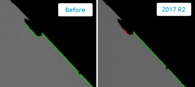
PC-DMIS 2017 R2 improves the efficiency of vision features by reducing rechecks caused by contamination. The outlier filter has been improved to better handle noise on small arc segments and at the end points of a line. The software can now correctly identify and remove those outliers requiring less manual analysis and rechecks from the programmer.

We’ve improved the efficiency of vision features by reducing re-checks caused by contamination. The outlier filter was improved to better handle noise on small arc segments, and at the end points of a line. We now correctly identify and remove those outliers requiring less manual analysis and re-checks from the programmer.
We introduced this new and improved outlier removal algorithm for lines and circles. The first step is an improved fit that is more robust to the presence of outliers. The new fit performs better for outlier removal, because it is less affected by large and/or concentrated and/or numerous outliers. The second step is an improved cutoff procedure for evaluating which deviations are outliers.
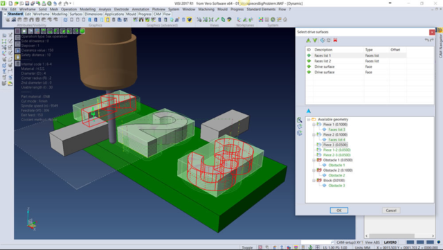
CAM Models from VISI can now be directly imported into PC-DMIS, complete with identified ‘Control Points’ that can be automatically converted to measurements.

CAM Models from VISI can now be directly imported into PC-DMIS, complete with identified ‘Control Points’ that can be automatically converted to measurements.
Tutorial Coming Soon…
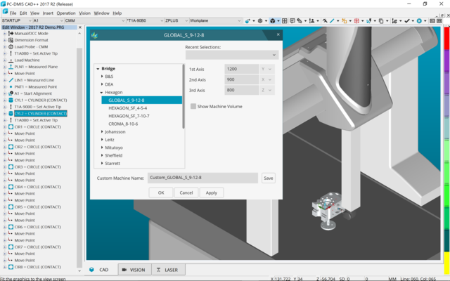
Importing CAD files is now multi-processor aware. More cores in your computer equals faster importing, and better experience overall. A new Virtual Machine dialogue is now organised in the tree view arrangement for easier machine selection with an added Table Only category so programming can be done even when the exact machine is not known. And a new CAD toolbar puts all the tools needed for CAD import and GD&T Selection in one place.

Importing CAD files is now multi-processor aware. More cores in your computer equals faster importing, and better experience overall.
Also, a new Virtual Machine dialog is now organized in the tree view arrangement for easier machine selection with an added Table Only category so programming can be done even when the exact machine is not known. And a new CAD toolbar puts all the tools needed for CAD import and GD&T Selection in one place.
Other CAD Improvements:
- You can use the tools in the Feature – Sensor Mapping dialog box to specify the sensor order.
- The Teamcenter interface supports the NX Direct CAD Translation (DCT), JT DCT, and CATIA V5 DCT translators.
- Swiftfix Vision components are available in the fixture library.
- If the Characteristic ID is activated in your license, an icon displays the Characteristic ID in the Graphic Display window.
- We added a Solid Edge DCT translator to PC-DMIS.
- A Cancel button is available when you import a CAD model through DCT. You can use this button to cancel the import of the model.
- The Cancel button is also available when you import an NX model through Direct CAD Interface (DCI).
Other Improvements
CREO Direct CAD Interface, 4-axis scanning, LSP-S2 Scan+ support, HP-THD Probe support, New SolidEdge CAD Translator, QuickScan support for laser probes, accuracy using HP-S-X5 HD with long extensions, a refreshed user interface and many more enhancements.
Recommended System Requirements
Attention 32-bit users! PC-DMIS 2017 R2 does not support the 32-bit Windows operating system, regardless of the operating system version number. PC-DMIS 2017 R1 was the final 32-bit version of PC-DMIS supported by Hexagon Manufacturing Intelligence. If you have not already done so, please update your measurement device operating system and hardware (personal computer), if necessary, to a modern 64-bit system with a more current and stable Windows operating system, such as Windows 10, Windows 8.1, or Windows 7.
Customers moving to a modern operating system will benefit from:
- Dramatically enhanced security
- Broad device choice for a mobile workforce
- Higher user productivity
- A lower total cost of ownership through improved management capabilities
Operating System
PC-DMIS 2017 R2 operates under 64-bit Windows 10, Windows 8.1, Windows 8, Windows 7, and Windows Vista. No other operating systems are supported.
Please Note:
- When you use third-party drivers, you should contact your local Hexagon representative to ensure operating system compatibility.
- Running PC-DMIS inside a Virtual Machine (VM) is supported only if the VM supports OpenGL 3 or higher.
- PC-DMIS Vision machines do not support 32-bit and 64-bit Windows 8.
- The Matrox Framegrabber PC-DMIS Vision hardware component does not support a 64-bit operating system.
Microsoft .NET Framework
Microsoft .NET Framework 4.6.1 for Windows. If you do not have Microsoft .NET Framework 4.6.1, the PC-DMIS installer will install it for you.
RAM
- 4 GB of RAM or higher
- The size of the CAD data file and the tessellation multiplier value used affect the amount of memory needed. These both affect the amount of tessellated facets needed to display the model. The smaller the tessellation multiplier value used, the more memory needed for the facets. For large CAD models, this could cause an ‘Out of Memory’ error. If this occurs, the current PC-DMIS session will be left in an unstable state and should be terminated.
- The default tessellation multiplier value is 1.0. Setting a tessellation multiplier of 0.1 will result in a 10 to 20 percent increase in the memory required over the default value of 1.0. Decreasing the tessellation multiplier further to 0.01 will result in an additional 50 to 65 percent increase of memory required.
- 1 GB of video RAM
CPU
2 GHZ or higher quad core processor
Graphics
- For desktops: NVIDIA Quadro K620 graphics card
- For laptops: NVIDIA Quadro K1100M graphics card
- For laptops running PC-DMIS with an RS4 laser sensor: NVIDIA Quadro M3000M graphics card with 4 GB of memory
Please Note:
The graphics driver must support OpenGL 3.0 or higher. A warning message appears on PC-DMIS startup if the driver does not support OpenGL 3.0 or if your graphics driver is more than a year old.
Hard Drive
- 2 GB of free hard drive space plus allocated virtual memory of eight times the largest CAD file used
- SSD drive, HDD 10K, or two disks in RAID 0 mode (high-performance hard disk drive)
Display
Screen resolution of 1280 x 1024 or higher
Connectivity
- Two Ethernet ports. This may be required for specific installations in consideration of local needs, including but not limited to CMM systems where one port is required for controller communications and another for intranet/Internet communications.
- Two USB ports
- DVD drive
- HASP key (a physical USB portlock) or a software licence
Please Note:
A HASP key does not act as general-purpose data storage; therefore, you cannot use a HASP key to store (download) arbitrary data from a computer. Similarly, you cannot use a HASP key to put (upload) arbitrary data on a computer. Also, only Hexagon Manufacturing Intelligence applications can read or write to a HASP key; other applications do not have this capability. As a result, you cannot use a HASP key to load and unload data to and from a computer.
Browser
Internet Explorer 10 or later
Antivirus Software
Hexagon Manufacturing Intelligence used the Sophos antivirus tool to test PC-DMIS 2017 R2. The user will need to confirm the performance of any other antivirus tool.
Solutions for CMMs Using RS-232 Communications
If you are installing PC-DMIS 2017 R2 on a new or existing computer, but you have an older CMM model that uses RS-232 communications, then you will need to install one of these solutions on your computer:
- An external RS-232 serial-to-USB adapter cable plus the serial-to-USB adapter cable driver
- An internal serial adapter card with serial ports
Related products
-
ReflectorCAD 1.5
$ 150.00 Add to cart Quick View -

NAPA 2013 Ship Design Software
$ 160.00 Add to cart Quick View -

Intergraph PV Elite V21 cracked version
$ 140.00 Add to cart Quick View -

Sescoi WorkNC 2016 with all add-ons
$ 175.00 Add to cart Quick View -

SOCET GXP 4.2.0 cracked full version
$ 160.00 Add to cart Quick View -
ASAP Pro
$ 150.00 Add to cart Quick View -

Lantek Workshop (Manager, Wos, Capture)
$ 150.00 Add to cart Quick View -
Sale!

Intergraph SmartPlant Electrical NEW cracked version
$ 180.00Original price was: $ 180.00.$ 135.00Current price is: $ 135.00. Add to cart Quick View -

Intergraph CAESAR II v11 cracked version
$ 120.00 Add to cart Quick View -

AEC Solution Packages cracked
$ 160.00 Add to cart Quick View


