CADmeister V11.0 provides improved operability, allowing the user to achieve “fast learning”, “stress relief” and “rework reduction”.
By activating two CADmeisters together, for example, the user can create a new design while referring to other data; and by displaying shading of the pre-selected area at the time of selecting surface entities, the visibility of images can be greatly enhanced.
The total modeling time has been significantly reduced thanks to the enhanced functions. CADmeister V11.0 features a new fillet forming function (patent-pending) that adjusts creases and folds found where the fillets join. Boolean operations for STL and solids as well as trimming STL on curved surfaces are other examples of improvements.
More functions to increase and improve operation efficiency have been added to our series of applications including CAM, mold and press mold.
CADmeister, a hybrid modeler capable of operating wire frame models, surface models, and solid models, performs set operations of mixed data of surface model and solid model, and enables modeling environments that are freed from the restrictions due to the differences in the types of data models.
Seamless use of surface models and solid models
CADmeister enables creating models that consist of wire frame models, surface models and solid models, without changing the environment.
It is capable of performing operations of solids and curved surfaces, to say nothing of the capabilities of performing set operations such as sum, difference and product among solids.
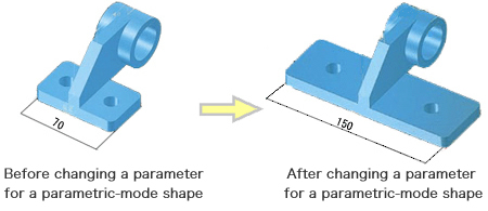
Unrestricted uses of parametric and non-parametric modes
The parametric mode enables users to change in design as well as design standard parts that have various nominal dimensions and design on the basis of the reusable parts of existing models.
Either of the parametric mode or the non-parametric mode can be chosen and used at the discretion of user.
In other words, users can flexibly design without being restricted by the procedures of parametric mode.
Even the imported data by IGES is able to be operated on the parametric mode for subsequent operations.
They can use the non-parametric mode in the middle of the modelling.
Flexibility of Customization
CADmeister can be flexibly customized and fit to the environment of user through several hundreds of environmental setting details. The script language dedicated to CADmeister enables the user to create their original commands and develop a database for their accumulated expertise for the use at CADmeister
Securing Data through the ‘Warm Start’ Feature
In case of a crash of CADmeister, the ‘warm start’ function enables a resumption of the job that failed to be saved immediately before the erroneous termination.
Solid Modeling
Solid Modeling is suitable for creating basic solids.
CADmeister enables creation of various types of solids such as draft solids, cylinders, cones, and helical solids.
Surface Modelling
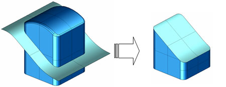
Shapes can be corrected efficiently through Surface Modeling that enables an operation by the unit of surface, not Solid Modeling.
Complicated shapes can be created more easily and efficiently through Surface Modeling than Solid Modeling.
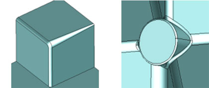
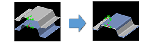
Filleting
CADmeister is capable of rounding part of a cross section or plane surface through the use of trochoid loci. Further, it is capable of forming a gradual fillet. (The “Fillet” command)
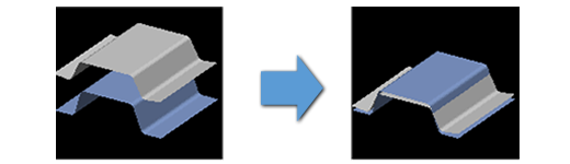
Gradual Filleting
Surfaces can be created for a junction of the surfaces by a single execution of this command, by specifying the target surfaces.
(The “Fillet_Gradation” command)
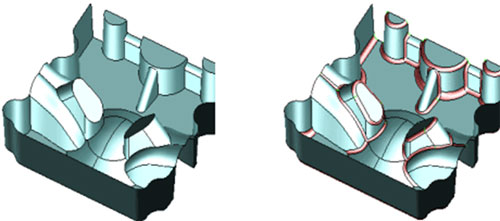
Automatic Filleting
Automatic Filleting By specifying a solid, this command automatically detects the ridges of the solid and creates a fillet for them.
This command is most suitable for creating fillets in the areas of drawing where R values have not been specified.
Subject to previously specifying R values at the target ridges before creating fillets, the ridges can be rounded at one time by a single execution of this command. (The Fillet_Auto” command)
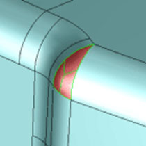
Collective Filleting
Multiple fillets can be created by a single execution of this Command if the same R value has been specified for them.
(The ” Fillet_Collective” command)
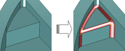
Filleting at Junction Points
This command easily creates a fillet at the junction parts of multiple boundaries. (The “Fillet_Branch” command)
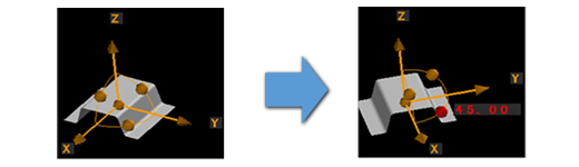
Contraction
CADmeister is capable of specifying the same extension scale for all of the axes, X, Y and Z or different extension scales for each of them.
Offsetting
CADmeister is capable of performing sophisticated Offset processes for complicated shapes. If there are areas that repel the Offset process due to the surface quality, CADmeister automatically recognizes the areas that accept the offset process and performs accordingly.
Measurement
CADmeister is capable of testing a slope angle, calculating weight and mass, and measuring distances among lines and surfaces.
Assessment
Numerous assessment commands for testing surfaces are embedded in CADmeister in order to confirm that there should be no swells or warps: curvature indication, indication of parameter fixed lines, indication of contours, search for undercuts, and indication of sections.
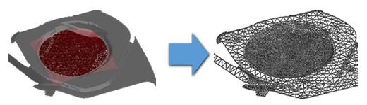
STL-EDIT consists of a batch of editing functions. It enables the use of STL figures that have been measured through 3D co-ordinate measuring instruments and imported into CAD system.
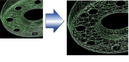
Simplification
The command enables a decrease in the number of elements in order to simplify the operation, without compromising the characteristics of STL figure’s shape. There are two methods for decreasing the number of elements: one by reduction rate and the other by target number of reduction.
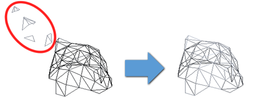
Noise Reduction
The command corrects a Face that has failed connection or a deformed Face that has a protrusion (referred to as ‘spike’) due to the impacts of noise during a measurement
* Deletion of Mesh Shells that Have Failed Connection
* Correction of the Protruded Vertex of Face
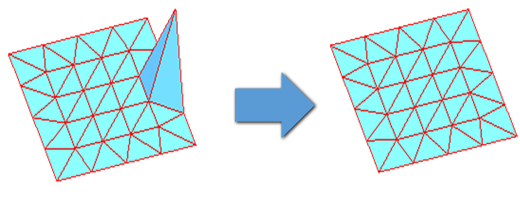
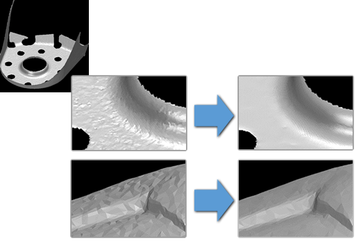
Smoothing
The command is capable of smoothing STL figures without impacting largely the shape of a portion rounded by executing a command for filleting.
Position Alignment
The three commands below relocate a target STL figure to a position where it overlaps an aimed element (STL figure or surface).
* Adjustment through the use of three points
* Automatic adjustment
* Manual adjustment
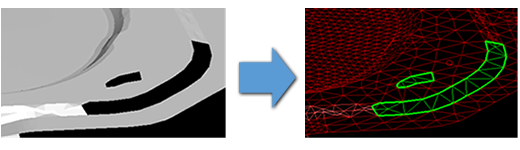
Filling in Holes
The 2 commands below fill up specified or all holes of STL figures.
* Filling in holes through simple operations
* Filling in holes through deformation analysis
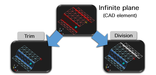
Trim
The command trims or divides a STL figure through the use of curves and infinite planes, elements of CAD system.
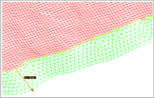
Extension
The command extends an STL figure by extending the external perimeter by a specified length.
* Extension command without specifications of areas
The command extends the whole area up to the indicated external perimeter.
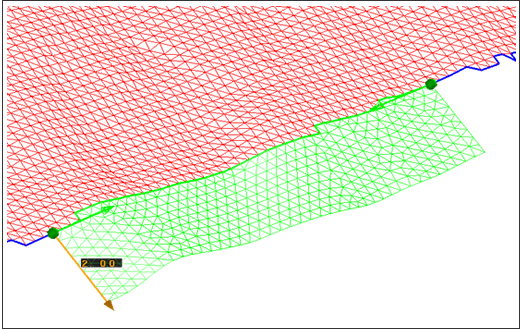
* Extension command with specification of areas
The command extends a specified area up to the indicated external perimeter.
CADmeister is equipped with various types of strong tools for data exchange that enable highly accurate exchanges of data with various types of CAD system.
CAD/CAM systems have their own strong points. Can you expect a smooth operation of CAD tasks if you purchase and use the same CAD system as your customer? The same CAD system may be useful for facilitating the exchange of CAD data between your company and the customer. However, if the system is only useful for designing models and suitable for architectural design, will it be enough to ensure the smooth operation of your CAD tasks?
Will the system be sufficiently capable of blending, drafting, contraction and offsetting? Further, will it be capable of 3D processing?
The priority placed on data exchange should not compromise the purpose of business. Means should not be the end. It is not a good solution to purchase CAD systems in order to meet the requirements of every new customer.
Our recommendation is to choose the CAD system that is most suitable to the business of your company, and then choose any optional data exchange function that is responsive to your customers.
Data can be exchanged directly or in the standard formats among different CAD systems.
Data exchanges in the standard formats
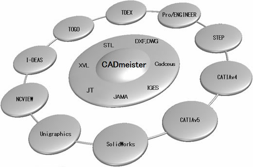
Typical intermediary formats that exchange data through standard formats are represented by IGES, JAMA, STEP, JT, STL or DXF.
Direct data exchange
A unique format of individual CAD systems is utilized for data exchange as it is. A converter is needed for each CAD system.
CADmeister has the standard and optional capabilities of data exchange.
Standard package of data exchange support formats
Import/export of IGES files
Import/export of JAMA-IS files
Import/export of DXF/DWG files
Import/export of CADCEUS files
Import/export of STL files
Export of XVL files
Export of VRML files
Optional package of data exchange support formats
(Separate licenses are needed.)
Import/export of STEP files
Import/export of CATIAv4 files
Import/export of CATIAv5 files
Import/export of Unigraphics files
Import/export of SolidWorks files
Import/export of JT files
Import/export of I-DEAS files
Import/export of Pro/ENGINEER files
Import/export of TDEX files
Import/export of TOGO files
Export of NCVIEW files
IGES , JAMA-IS
CADmeister is capable of choosing recommended parameters that are fit to the CAD system that receives and returns data. It enables correct data exchanges
DX , DWG
CADmeister can utilize conversion parameters in order to enable various types of settings for these files.
CADCEUS
CADmeister can input into CFIO files of CADCEUS the data such as of placement, layer, and history. Also, it can output CFIO files of the indicated objects (parts, assemblies, sheets, views). The output CFIO files contain non-parametric mode data that do not have history data.
STL
STL (Stereo Lithography) is a standard format for laser beam lithography. CADmeister can convert solid data into STL (text/binary) format data. STL data are used for the commands such as explicitly describing distances among STL elements and changing the shapes of STL figures.
XVL
XVL (eXtensible Virtual world description Language) is a 3D data format developed by Lattice Technology Co.,Ltd.. XVL Player is needed in order to confirm the files of XVL format.
VRML
3D CAD data such as of revolution and extension can be confirmed through web browsers, provided that they are of VRML. VRML data are useful for meeting with customers as well as the other departments of a company.
STEP
STEP is a file format compliant to ISO international standards that regulate the expressions and conversions of model data. The convertible STEP files are AP203 and AP214.
AP203 enables conversions of model data (points, lines/curves, surfaces, composite surfaces, solids, assemblies).
AP214 enables conversions of model data (points, lines/curves, surfaces, composite surfaces, solids, assemblies) and attributes of shapes (display attributes, groups, and layers).
CATIAv4
The standard external file format for CATIA Ver 4 is Model File (*.Model).
Import :The CATIA Model File, Sequential File(*.exp) support version is Ver4.2.5.
Export : The CATIA Model File support version is Ver4.2.5.
CATIAv5
The standard external file format for CATIA v 5 is CATPart file (*.CATPart).
The standard assembly file format for CATIA v 5 is CATProduct file (*. CATProduct).
Import :The support versions are R13 through to R24.
Export :The support versions are R13 through to R23. Note: The software “CATIAv5 Translator” provided by UEL Corporation is needed.
Unigraphics
Import
The Parasolid format(*.xmt_txt,*xmt_b)support versions are Ver.7.0 through to Ver.28.0.
Export
The conversion format(*.xmt_txt) is Parasolid format Ver.7.0.
SOLIDWORKS
Import
The Parasolid format(*.x_t,*x_b)support versions are Ver.7.0 through to Ver.28.0.
Export
The conversion format(*.x_t) is Parasolid format Ver.7.0.
I-deas
Import /Export The intermediate file is ENF format(*.armo,*.enf_ide).
Note:
The corresponding software products 「Elysium DirectTranslator」 need to be installed on the side of I-DEAS.
「Elysium DirectTranslator EX7.0」 support versions are NX I-deas 6.3,6.4,6.5.
Pro/ENGINEER
Import /Export The intermediate file is ENF format(*.armo,*enf_pro).
Note:
The corresponding software products 「Elysium DirectTranslator」 need to be installed on the side of Pro/ENGINEER.
「Elysium DirectTranslator EX7.0」 support versions are Wildfire 5.0 , Creo Parametric 2.0, 3.0.
JT
Shape data (points, lines/curves, XT B-Rep, JT B-Rep) and polygonal data (polygons, polygonal lines/curves) are converted into JT format.
TDEX
This is the file format for data transfers regulated by Toyota Motor Corporation.
TOGO
This is the file format for the comprehensive CAD/CAM system (TOGO) developed by Toyota Motor Corporation.
NCVIEW
This converts into the data formats that can be handled by the machining simulation system developed by Ai solutions Co, Ltd.
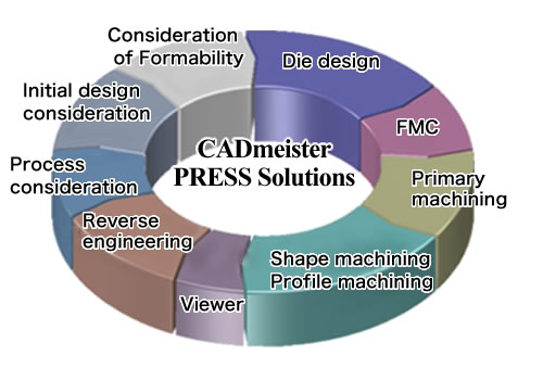
The module supports designing press dies. It consists of three key function items: design support, modeling support, and post-process support.
This module is for a stress analysis which enables seamless operations between CAD and CAE for designers. Designers can perform stress analyses through simple input CAD operation without being concerned with CAE.
This is a simple simulation capability for shaping a press die. This enables a quick understanding of ‘Blank Deployment Lines’ and ‘Flange Deployment Lines (Trim Deployment Lines)’ that will help quotations at the initial stage of designing.
DL enables three-dimensional supports. It is used for the design stage for improving quality of DL design
This enables quick and precise modeling in order to help users shorten the delivery time.
It can form and model by taking into consideration the characteristics of press die forming, empty-weight deflection (that is needed for confirming interference against die parts when transferring panels), material characteristics, and STL figures.
PRESS-FORM-PLUS-II enables direct references to the results of simulation analyses of sheet metal forming (in the form of NASTRAN format file) in order to improve the preciseness of forming at the initial stage.
DRAW-DIE-EX can shorten a designing phase through the use of Dynamic Navigator,
navigation tool, regardless of the skills of individual users.
PRESS-MOTION enables designers to analyze transfer lines through simple operations.
This is a tool for confirming the attribute data that have been assigned to 3D CAD data (such as the information of materials and unit prices).
CAM-STRUCTURE is capable of creating data for machining a ferrous die for accepting a press die through simple operations on solid data. (Note that the ferrous die is referred to as a ‘Structure’ and the press die is referred to as an ‘Insert’.) CAM-STRUCTURE improves the precision of machining a Structure and reduces workloads.
FM-CAM2 is a support tool for processing full-mold models through an effective use of 3D solid models.
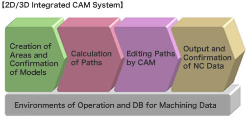
CAM2D is capable of seamlessly integrating the features of CAD and CAM systems.
It enables users out in the manufacturing field to create 2D machining paths which are used for the commands of ‘Profile Machining’,’Pocket Machining’ , and ‘Hole Machining’ through simple operations.
CAM3D creates data for machining curved surfaces of 3D CAD models that consist of surfaces as well as solids.
3DPROFILE has various 3D capabilities of machining and interference prevention.
It supports automatic profile machining from preliminary rough processing through to finishing.
CAMEDIT has various types of editing capabilities.
It enables users to edit paths highly efficiently through easy operations.
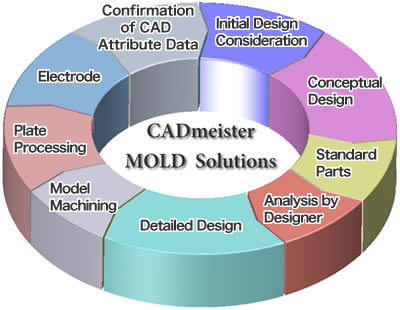
MOLD CREATOR can be used for each phase of structuring a mold: initial design consideration, considerations of cavity and core, conceptual design, detailed design, creation of drawing, preparation of data for order placement.
CADmeister-LITE enables users to input directly CAD attribute data (part attributes, machining attributes, and tolerance attributes) that have been provided to groups of parts and individual parts, provided that the parts have been designed through the use of MOLD CREATOR.
MOLD-FORM enables designers to rectify poorly shaped portions of resin models partly due to sink and warpage through the use of the simulation results of shaping.
CAE-MOLD presents a collection of seamlessly integrated CAD and CAE functions such as analysis of mold cooling and analysis of mold bend. CAD shapes can be used as they are on the CAD system screen. Professional CAE expertise or skills are not needed to execute the functions.
CAE-INJECT enables resin flow analyses by utilizing CAD shapes on the CAD screen as they are without data conversion. Also, it enables confirmation of results through the same operation of CAD commands. Thus, this tool enables mold designers to improve the accuracy of judgment and shorten the lead time.
DENKYOKU-CAD provides a full support for all phases of: creating mold, considerations and shaping of electrode parts, and preparing documented instructions in order to perform electric discharge.
DENKYOKU-CAM provides a one-stop support for all the phases from CAM calculation through to interference check after NC (numerical control) output. This is enabled by an intuitive operation of dragging attribute data that have been given to electrode models and dropping them to a subject database for machining.
CAM-ATTRIBUTE automatically creates and standardizes data for hole machining based on the 2D/3D attribute data and geometric data that have been assigned for hole machining.
CAM2D is capable of seamlessly integrating the features of CAD and CAM systems. It enables users out in the manufacturing field to create 2D machining paths which are used for the commands of ‘Profile Machining’, ‘Pocket Machining’, and ‘Hole Machining’ through simple operations.
CAM3D creates data for machining curved surfaces of 3D CAD models that consist of surfaces as well as solids.
CAMEDIT has various types of editing capabilities. It enables users to edit paths highly efficiently through easy operations.
CAM3D creates data for machining curved surfaces of 3D CAD models that consist of surfaces as well as solids.
CADmeister/CAM provides operational modes for skillful expert users and beginners.
Capabilities of creating NC Data that support ‘3-axis machining devices’ , ‘Table 5-axis machining devices’ , and ‘Attachment 5-axis machining devices’ are provided.
CAMEDIT has various types of editing capabilities. It enables users to edit paths highly efficiently through easy operations.
CAM2D is capable of seamlessly integrating the features of CAD and CAM systems. It enables users out in the manufacturing field to create 2D machining paths which are used for the commands of ‘Profile Machining’ , ‘Pocket Machining’ , and ‘Hole Machining’ through simple operations.
CAM-DX supports high-speed and high-quality machining methods as well as the conventional machining methods. Thus, CAM-DX can respond to a wide variety of users’ needs.
CAM-ADV enables work flows without wastes and reworks, provided that it is operated as an add-on function for CADmeiser/CAM.
3DPROFILE has various 3D capabilities of machining and interference prevention. It supports automatic profile machining from preliminary rough processing through to finishing.
CAM-STL creates paths on the basis of STL figures such as measurement results and models that consist of combinations of surfaces and solids.
CAM-STRUCTURE is capable of creating data for machining a ferrous die for accepting a press die through simple operations on solid data. (Note that the ferrous die is referred to as a ‘Structure’ and the press die is referred to as an ‘Insert’.) CAM-STRUCTURE improves the precision of machining a Structure and reduces workloads.
FM-CAM2 is a support tool for processing full-mold models through an effective use of 3D solid models.
CAM-ATTRIBUTE automatically creates and standardizes data for hole machining based on the 2D/3D attribute data and geometric data that have been assigned for hole machining.
FM-CAM2 is a support tool for processing full-mold models through an effective use of 3D solid models.
This tool is capable of inheriting and using data of 3D solid models that have been designed through the use of ‘CADmeister/PRESS’ or ‘CADmeister/MOLD’.
The data pertain to assembly structures (hereinafter also referred to as ‘ASSY structure’) and attributes of parts (hereinafter also referred to as ‘Parts attribute’ ).
JIG-PKG optimizes the design and manufacturing of inspection jigs.
It provides enhanced functions dedicated to inspection jigs by utilizing the strong modeling functions of CADmeister.
This offline teaching system enables users to create NC (numerically controlled) programs and jigs for simultaneous 5-axis laser machining using the minimum workload through the use of 3D CAD data.
This CAD offline teaching system enables users to code programs for automatic measurement through the use of 3D measuring instruments.
The management of all data pertaining to design and manufacturing can be integrated.
The subject data include the data of CADmeister, various types of document files, and other CAD/CAM system data files.