
Lantek Flex3d (Steelwork, Tubes, 5x, CAD Addins, Unfolding)
$ 175.00
Lantek Flex3d is the most flexible 3D CAD/CAM software, totally engineered by Lantek and conceived for automating the CNC programming for 3D machining tubes, pipes, beams, profiles, and sheet metal.
Lantek Flex3d provides the most advanced nesting algorithms and machining strategies (Thinkingmetal Technology) and performs at excellent level with machines of any of the existing technologies: laser, plasma, saw, oxy-fuel or water jet, even combined with complementary tools like drilling, marking, milling, tapping and others.
Lantek Flex3d achieves an outstanding performance with our Machine Tool Builder Partners, based on our close collaboration with them, but also optimizes the results of machines from manufacturers like Amada, Boda, Bystronic, Daito, Dardi, Farley, Ficep, Geka, HanKwang, Hans Laser, HGG, Kotec, Mazak, Microstep, NTC, Peddinghaus, Prima Power, ProArc, Promotech, Stako, Trumpf, Vanad, Voortman, and many other.
Lantek ensures excellent results for any machine today and in the future.
Description
Lantek Flex3d Steelwork
 The structural steel sector is responsible for designing the large structures of our world. Our lives depend on the efficacy of the structures produced by this industry, which adheres to stringent regulations. Lantek Flex3d Steelwork is sophisticated software designed to control the production and manufacturing of steel products and prefabricated structures.
 Product Specifications
Easy and Flexible Design
Lantek Flex3d Steelwork includes 2D and 3D design, CNC programming of profiles, integration with third party structural design software, and ERP capabilities to control costs and optimize return on investment. This module, when integrated with the Lantek Flex3d Steelwork System, facilitates the 3D CAD/CAM design and cutting of standard profiles including: I, U, L, H, T, and square or round tubes. The automatic and semi-automatic features of the 3D nesting software maximize the use of materials and optimize the CNC code with collision avoidance technology as well as safe and efficient cutting operations on a wide range of machinery such as: sawing, drilling, punching, tapping, marking, oxy-cut, and plasma equipment.
Once the design process is completed, the user can simulate the head movement of the machine, the beam or tube movement, and the machining operations of every tool in 3D. The user can also generate the NC file and send it directly to the machine. Lantek Flex3d Steelwork can be adapted to work with any beam or tube machine.
When Lantek Flex3d Steelwork is linked with Lantek Expert, it can design nest and CNC program 2D sheet metal profiles. This software includes a wide range of functionality such as automatic and manual nesting, lead-in contour management, common line cutting, tool path transformation, CAD interfaces and layer management. When linked with Lantek Integra ERP technology, Steelwork enables management to have process and cost controls from any location with Internet service.
This is a module of ultimate flexibility that brings together design, manufacturing and production management. The harmonic created with this software permits companies to operate more efficiently, to deliver projects on time, to control costs, and to achieve profitability goals.
-
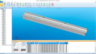
Beam part
Technical Characteristics
Lantek Flex3d Steelwork is a system that includes database technology. This eliminates the need for the user to continuously duplicate the entry of information to create a beam or tube section. The parametric technology of this system allows the user to select a base section and then modify the measurement. The result is complete management of different profile products and remnants that are rapidly available on file.
While Lantek Flex3d Steelwork may be a standalone product, it is maximized when integrated with the Lantek Manager andLantek Integra Management Software Systems (MES/ERP). This integration incorporates features that start at the sales quotation level (jobs or projects) and continues with the launch of orders and production flow including: material needs, reservation management, purchases, and cost controls. It also incorporates workshop data collection, the integral management of warehouses, inventory of beams, sheet metal, tubes, remnants, commercial products, and finished goods. The system has total traceability management.
DSTV, SAT and CAM Importers
Lantek Flex3d Steelwork imports data generated by the leading structural steel CAD systems using DSTV, SAT and CAM files. The system converts the DSTV, SAT and CAM files into the native format for Lantek Flex3d, which easily allows the user to apply modifications. In addition, this module will import various properties of a file, such as the material, quantity and thickness — all of which simplify the process for cutting preparation.
-
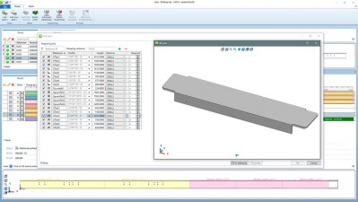
Import parts
Design Options
Lantek Flex3d Steelwork not only performs basic operations such as drilling, shearing, marking and sawing, it also creates cutting operations from geometry imported from the Lantek 2D module and imports file formats such as DXF.
Lantek Flex3d Steelwork performs the following operations:
- Automatic and Semi-automatic drilling, tapping, and sinking operations along the profile (any flanges and/or web)
- Automatic and Semi-automatic cutting operations (plasma, oxycut, sawing or shearing)
- Automatic tools for text and contour making operations (scribing, contour marking, plasma)
- Cutting macros, which include parametric operations and drive any 5 or 6 axis cutting head (bevel cutting)
- Stored machining along the beam or tube section, which keeps the related profile for easy modification
Optimization and Profile Cutting
Lantek Flex3d Steelwork allows the user to obtain the optimized profile path and to generate the CNC file for the machine.
The system is optimized further by importing sections from the warehouse automatically or by calculating the supply needs.
Lantek Flex3d Steelwork offers tools that automatically detect and control collisions as well as make manual modifications.
Also, there are several relevant reports and process forms generated for the convenience of the user.
-
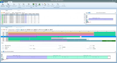
Jobs module
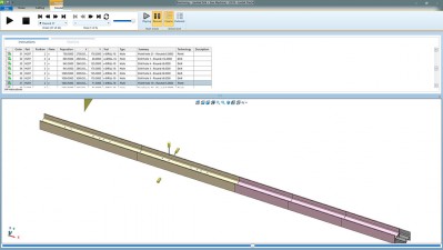
Cutting Profiles Simulation
Lantek Flex3d Steelwork allows the user to simulate each machining operation whether it is drilling, punching, the cutting head, or the work zone. If the resultant simulation is acceptable to the user, Lantek Flex3d Steelwork will automatically generate the NC file for the machine and the user can view this data in the same environment. As seen in the illustrations, the simulation is of all machining operations and the trajectory of the cutting head (plasma or oxy-cut). When collisions are found, the user can repair them by stopping the simulation and correcting the trajectory.
The user can see all of the parameters of cutting during the simulation and, while viewing, make zoom movements, rotations or axis positioning adjustments to the profile. Viewing is totally interactive during simulation with options for viewing step-by-step, forward or rewind.
-
Simulation
Lantek Flex3d Tubes
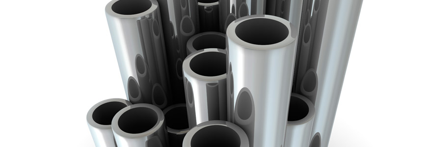 Lantek Flex3d Tubes is a CAD/CAM software system for designing, nesting and cutting parts of tubes and pipes.Lantek has used all of its experience and proficiency gained in design systems and programming for sheet metal cutting, punching and bending machines and applied it to the tube cutting sector – regardless of the type of machine.
 Product Specifications
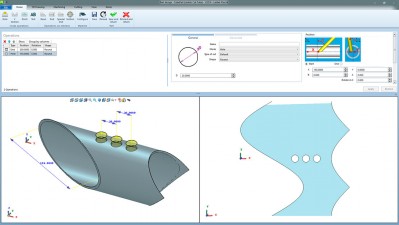
Easy, Flexible Design
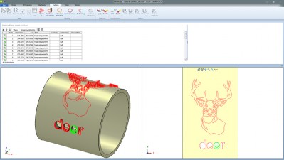
Lantek Flex3d Tubes integrates with various kinds of tubular geometry importers such as SAT and IGES. This software allows 3D design to be simple and intuitive. It gives a true vision of the resulting design profile that will eventually be cut on a machine.
This system is a parametric system which allows the user to change the values of any operations previously made, including changes to the initial parameters of each tube (lengthening, shortening, change of diameter).
Once the design stage is complete, the user can simulate optimization of the tube (nesting) and the path followed by the cutting head. The software will directly generate the NC program in order to send this optimization to the machine.
Lantek Flex3d Tubes adjusts cutting information based on the characteristics of the machine such as the number of applicable axis (3 axis, 5 axis, etc.)
-
Part design
-

Part design
Technical Characteristics
- Provides a real vision of the expected result on the screen
- Displays the exact tube and simulates 3D and each process, thus reducing errors
- Allows for easy manipulation and editing of the design with zoom, view, and rotation controls
- Offers the user the ability to create standard tubes based on requirements
- Allows the user to design tube types adapted to their needs from 2D outlines, in addition to cylindrical, rectangular, and triangular tubes
- Allows for the design or import of desired geometry to create any type of cutout or trim with 2D design options
- Offers a dynamic coordinate system tool, which is specific for tubes, and offers various options to configure the coordinate system
Lantek Flex3d Tubes is totally integrated with Lantek’s management systems, Lantek Manager and Lantek Integra. This system integrates management of the sales process from quotations through invoicing. It also includes sales orders, manufacturing operations, resource management, material requirements, purchasing processes, production planning, and time and cost controls.
It is also possible to incorporate workshop data collection and to integrate it for a total management package. This includes management of warehouse/stock (profiles, sheet metal, tubes, remnants, commercial product and finished goods). Additionally, the system includes serial and batch numbers for complete traceability management.
-
Part design
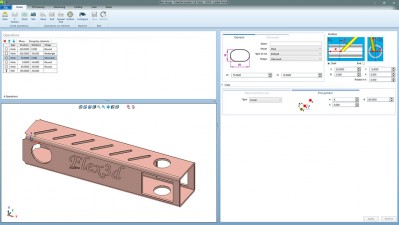
Design Options
- Complete or partial chamfers on either end of the tube
- Possibilities for creating any type of contour (round, rectangular, triangular, etc.) either projected through one or both faces at any point on the tube, at any angle
- Various options for copying elements and operations (linear, circular, by grid)
- Visual identification of intersections and operations with easy calculation of intersections between two tubes
- 2D geometry projected or surface mapped on the tube surface
- Data modification checked and modified at any time in the operations tree
-
Design options
Optimizing and Cutting the Tube
Lantek Flex3d Tubes allows the user to obtain the best optimization of both the tube itself and the generation of the NC file for the machine. Optimization is created by importing sections from the warehouse automatically or by calculating supply needs.
Other features include:
- Remnant management
- Warehousing and Re-utilization
- Automatic, semi-automatic or manual 3D nesting
- Automatic or manual lead-in and lead-out generation
- Profile management and subsequent operations along the length of the tube
- Support for machines with various number of axes
- Integrated management of different machining technologies such as: bridges, micro-joints, cutting qualities – all managed manually, semi-automatically, or completely automatically
- A versatile environment for the machining process which can be achieved in 2D or 3D
- Machine technological parameters which are specified in material dependency tables and totally user-configurable
- Several reports which provide relevant information for the user
- Calculated contour cuts which may be accomplish automatically by the system or manually by the user
-
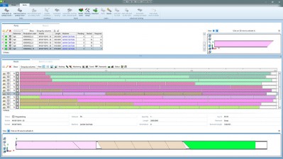
Nesting
CNC Simulation and Generation
Lantek Flex3d Tubes can simulate the cutting machine and the machine sequence over the tube. If the resultant simulation is acceptable by the user, Lantek Flex3d Tubes will automatically generate the NC file for each machine; and, in the same environment, it will integrate the information related to the design and post-processing. Lantek Flex3d Tubes offers totally interactive simulation: step-by-step, forward, rewind, pause, and restart.
-
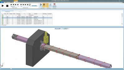
Simulation
Lantek Flex3d 5x
 Lantek Flex3d 5x is a special application from the Lantek Flex3d family of products for the automatic programming of five-axis machines using laser and water jet technologies. Lantek Flex3d 5x is the result of over 15 years of working experience in close collaboration with both manufacturers and users of this type of machine.Lantek Flex3d 5x is compatible with the most widespread 3D design systems. It allows the import of parts from every International standard format and defines the desired technology for the subsequent cut generation. Designed to operate on PC based systems, Lantek Flex3d 5x interface is similar to the other products in the Lantek family. As a result, the software requires a short learning period and it is very easy to use. The user simply has to follow the instructions provided by the software itself.
 Product Specifications
Technical features
- Solids and surfaces supported formats: SAT, IGES, VDA, STEP, Parasolid, CATIA, SolidWorks, Solid Edge, Inventor, NX and ProE (Creo Elements)
- May share a common database for machines and materials with Lantek Expert
- Automatic detection of the part cutting contour and thickness
- Multiple options to place the part on the machine table
- Different cutting qualities can be set by contour or by portion within the same contour
- Multiple possibilities to change head position in each point
- Lead-ins, lead-outs and micro-joints/tabs
- Rapid movements automatically or manually adjusted
- Simulation of complete working environment: part, table, fixtures, head, etc.
- Collision check and automatic avoidance of collisions
-
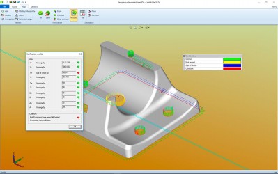
Verification status
Automatic fixtures calculation
Lantek Flex3d 5x automatically generates the fixtures necessary for positioning the part correctly on the machine table.
Taking as a base the desired position and height of the part above the cutting table, the system provides a user-modifiable holding grid, where the user can decide how many fixtures will hold the part in place and their locations.
When the appropriate holding grid has been designed, Lantek Flex3d 5x generates the solids necessary for positioning the part on the table. Automatic fixture calculation takes cutting contours into account, so that the calculated fixtures do not interfere with either the cutting head or any of the holes to be cut. This saves valuable machine time, normally associated with program verification in the machine.
These fixtures can be revised in 3D mode. The design or the position of the fixtures can be modified and recalculated at any stage of the process.
When the correct fixtures are in place, the user can automatically transfer the 2D geometry to Lantek Expert Cut or Lantek Expert Punch for the parts to be cut on any available machine.
Machining
Lantek Flex3d 5x automatically detects all the part cutting contours, allowing automatic or semi-automatic machining of these contours. The qualities to be applied to each contour can also be selected by user. The automatic machining sequences and model intelligence is generated irrespective of where the 3D CAD design data originated. As a result, Lantek Flex3d 5x enables manufacturing of products directly from design data, eliminating potential errors.
After machining, the system allows entire work environment simulation. The software and post-processors include a three dimensional model of the appropriate machine and cutting head. Lantek Flex3d 5x automatically detects any possible collisions of the head with any other elements involved in the cutting operation, offering multiple possibilities for correcting them. The physical limits of the axis are also considered during the whole process.
Lantek Flex3d 5x permits full cutting direction change. Any cutting vector can be modified, erased or inserted at any point of the contour so it prevents unwanted movements and positions.
-
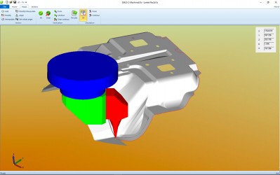
Machining simulation
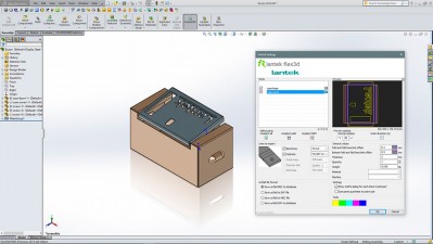
Lantek Flex3d Addins
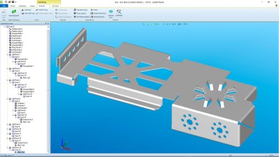
 Lantek Flex3d Addins import native CAD drawings from popular CAD systems such as: SOLIDWORKS®, Solid Edge®, Inventor®, Catia®, and Creo Elements/Pro™ (formerly Pro/ENGINEER) for the automatic unfolding of any sheet metal design in 3D. This solution is ideal for integrating the user’s 3D models with Lantek CAD/CAM/MES/ERP. It is a powerful, direct, and intuitive way to avoid unnecessary file generation.The unfolding of both individual parts and sets of parts (assemblies) is included in this module, which is also capable of exporting the assembly structure with a fully structured parts and materials list. The set of parts imported with Lantek Flex3d Addins may consist of various materials and thicknesses. Unfolding is direct to the Lantek database and eliminates the need for intermediate DXF files.After part unfolding and prior to the final transfer to the Lantek management system, the user can see a preview of each flat pattern.Total association remains constant between 2D and 3D in this module. Any modification to the 3D file is automatically and accurately reflected on the 2D part within the Lantek system.
Designed for both subcontractors and companies who manufacture their own products, Lantek Flex3d Addins form part of a design environment that encourages productivity, creativity and design.
Lantek Flex3d Addins are capable of identifying sheet metal items and performing the unfolding automatically with the assigned thickness and material type.
During the unfolding process, the system shows the folding lines, the limits per fold, and part contour, and assigns relevant technologies to each.
Product Specifications
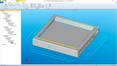
Integration
Parts and assemblies generated with Lantek Flex3D Addins are directly transferred to the Lantek Manager and Lantek Integramanagement systems for integrated manufacturing and management processes, as well as to the Lantek Expert system for material and machining optimization processes. Between both systems, Lantek offers a complete solution, which includes 3D part design through to CNC generation per machine type.
-
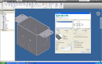
Autodesk Inventor
-
Solid Edge
-
SOLIDWORKS
Lantek partnership
SOLIDWORKS – Solution Partner
Lantek has acquired Solution Partner status, which means that Lantek Flex3d Addins complements the SOLIDWORKS® system, providing it with functions of specific interest to companies working in sheet metal processing.
Solid Edge – Voyager Member
Lantek has acquired Voyager Member status, which means that Lantek Flex3d Addins complements the Solid Edge® system, providing it with functions of specific interest to companies working in sheet metal processing.
Autodesk Inventor – ADN Member
Lantek has acquired ADN Member status, which means that Lantek Flex3d Addins complements the Autodesk Inventor® system, providing it with functions of specific interest to companies working in sheet metal processing.
SOLIDWORKS® and CATIA® are registered trademarks of Dassault Systèmes S.A.
Solid Edge® is a registered trademark of EDS/PLM Solutions.
Autodesk Inventor® is a registered trademark of Product Lifecycle Management Software, Inc.
Creo Elements/Pro™ (formerly Pro/ENGINEER) is registered by Parametric Technology Corporation (PTC).
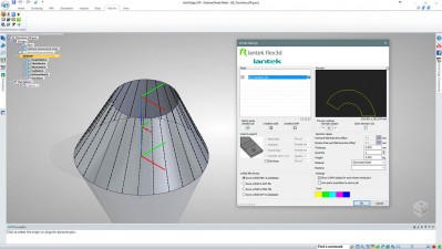
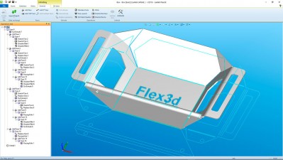
Lantek Flex3d Unfolding
 Lantek Flex3d Unfolding is a software application which enables 3D design of folded sheet metal parts and generates their subsequent automatic unfolded design.Lantek Flex3d Unfolding is a stand-alone application and no additional software is needed to work with it.
 Product Specifications
Technical Characteristics
- Dynamic coordinate system specifically for boxes.
- Real viewing of the part.
- Powerful 2D design module.
- Automatic unfolding. Possibility of unfolding (transfer from 3D to 2D geometry) in DXF or Lantek’s own data format used within Lantek Expert.
- Creation of the base face from 2D geometry or parameters introduced by the user.
- Parametric addition of any type of face to the base face:
- Individual offsets at both ends of the added face.
- Chamfers at each end of the added face.
- Corner radii for each one of the faces.
- Different angle input for each one of the faces.
- Multiple options for dimensioning the faces.
- Face types which grow outwards, inwards or exactly to the edge.
- Automatic rectangular or semi-circular cutaways.
- Creation of faces at 0º and 180º.
- Creation of multiple faces from one profile.
-
Folding operations
-
Folding operations
-
Folding operations
Easy, flexible design
With Lantek Flex3d Unfolding, the design of any part in 3D is made simple. Starting from a solid base, the different faces are added to form the complete part. Once the part has been designed, the unfolding is immediate and automatic. The application has a powerful help system with detailed explanations of each one of the options, so that the user may resolve any doubts quickly and simply.
Construction options
- Creation of extrusions. Creation of faces from 2D geometry.
- Cutting of extrusions.
- Creation of standard holes or design of their geometry in 2D. Creation of dies for holes.
- Standard form tool library, with the ability to create additional dies.
- Rounding (filleting) of the parts in 3D.
- Automatic mitring (diagonal, 90º, 2D geometry) on two superimposed faces. This utility allows two superimposed faces to be separated.
- Lengthening and shortening of 2 faces
- At a set value.
- To a parallel plane.
- To a non-parallel plane, with and without reference.
- To a vertex.
- Lengthening and shortening of 2 faces until they meet.
Unfolding options
Automatic unfolding of the part based on its own unfolding rules, which depends on:
- The K factor.
- A technology table which can be configured by the user, in accordance with thickness, radius, and the machine.
The unfolding provided by Lantek Flex3d Unfolding is totally configurable.
There are two output formats:
- Unfolding of geometry to DXF format file, completely user-configurable from the program (type of line, color).
- Direct unfolding to Lantek Expert‘s data base (MEC). No need to create intermediate files. The system allows the 2D geometry obtained to be directly transferred to the CAM cutting or punching system.
Related products
-

Shoemaster QS14.01 full cracked version
$ 170.00 Add to cart Quick View -
Sale!
ONBOARD PROGRAMS
Original price was: $ 5,800.00.$ 180.00Current price is: $ 180.00. Add to cart Quick View -
GPRSIM v3.0 cracked version
$ 130.00 Add to cart Quick View -
Sale!
DRAWings 8 Pro cracked version
Original price was: $ 1,800.00.$ 140.00Current price is: $ 140.00. Add to cart Quick View -
Intergraph PV Elite V21 cracked version
$ 140.00 Add to cart Quick View -
Sale!
Wilcom Embroidery Studio E3 Designing cracked with dongle emulator
Original price was: $ 3,000.00.$ 110.00Current price is: $ 110.00. Add to cart Quick View -
Sale!
Wilcom DecoStudio E3 cracked with dongle emulator
Original price was: $ 2,000.00.$ 120.00Current price is: $ 120.00. Add to cart Quick View -
Sale!
Intergraph TANK NEW cracked version
Original price was: $ 180.00.$ 150.00Current price is: $ 150.00. Add to cart Quick View -

ETAP 14.1 cracked version download
$ 140.00 Add to cart Quick View -
GPR-SLICE v7.0 cracked radar software
$ 160.00 Add to cart Quick View