
EUKLID CAD/CAM V22 crack now available!
130 $
Since the end of January our current CAD/CAM solution is available for download. EUKLID CAD/CAM V22 contains numerous improvements and performance enhancements:
- filter function by color and type
- new LCS functions
- new milling function MF3Corner, MF5Corner and MF5UValternate
- new engraving milling function ME5Pocket3D and ME5DOTCS
- optimization of milling function MF3UV and MF5UV
- optimization of milling function MRough2 and Adaptive Roughing
Description
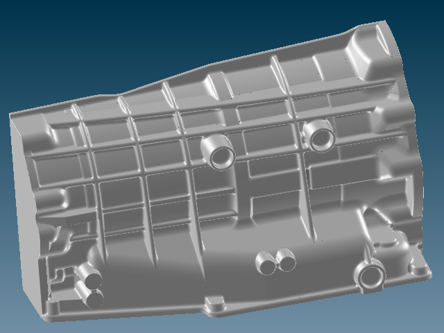
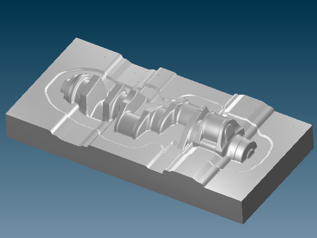
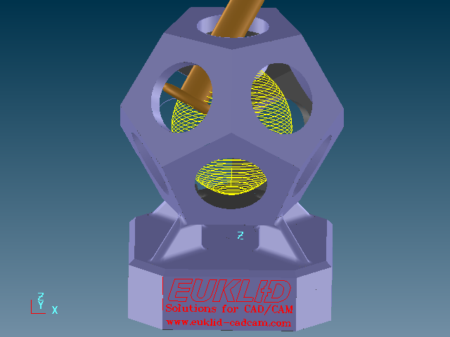
Machining free-form surfaces. As precise as a Swiss watch!
Some CAD/CAM visions can only be understood by experts. Our visions make you an expert: EUKLID has been offering solutions since 1970. Solutions which other producers have been unable to develop. Today 5-axis milling machines are common, but it is difficult to find 5-axis milling experts. Euklid software and our specialists make it easier for you to work with the milling machine … because 40 years of expert knowledge pays off!
Today’s milling machines are very powerful and have the potential to do more than just standard jobs. On the other hand, current CAM systems do not make use of their full capabilities. The more complex the job is, the more important mathematics becomes. The exactitude and quality present in Euklid’s software solutions, coupled with the brain power of your dialog partners, really helps you and your staff.
Ask Euklid, ask us. Challenge us! Each surface-milling job, even the most complicated ones, has its solution. It’s only a question of the correct software and of the experts supporting you.
EUKLID CAD/CAM
EUKLID CAD/CAM is a highly efficient 3D CAD/CAM system for tool, mold and model making which, in the long run, guarantees you important cost, time and quality advantages.
Since 1979, Euklid has been an industry pioneer and pace setter, setting a high standard practice-oriented 2.5- to 5-axis machining and easy to manufacture 3D-model making. The broad application spectrum enables the tool, mold or model making company to realize high productivity improvements because it runs all existing CAD/CAM tasks quickly and precisely.
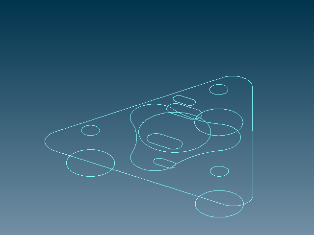
CAD Definition
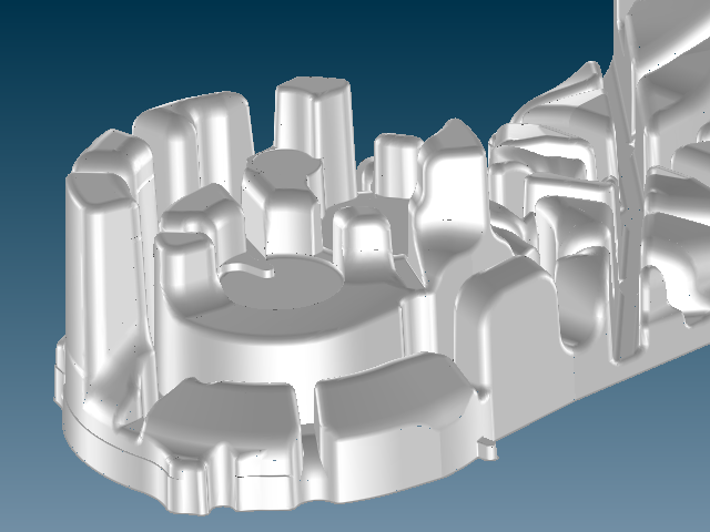
EUKLID CAD/CAM offers unrivaled user support, with a wide variety of functions for creating easy to manufacture surface models. Additional industry-specific functions (forge, cast, impeller and tire) allow fast and efficient knowledge transfer.
All CAD-functions offered by EUKLID CAD/CAM are practical, highly efficient and easy to learn and understand. Two major benefits of using EUKLID are the high degree of flexibility offered and the ease with which later modifications can be made. Of course, functions for volume calculation, shrinking of models and pattern partition are included in basic EUKLID. Processing most demanding surface models with highly complex blendings and draft surfaces is a specialty of EUKLID CAD/CAM.


Geometry Definition
All functions creating surfaces are ideally suited for tool, model and mold making. The technologically necessary blendings, surface transitions and draft surfaces are created in a practical and flexible way. Also EUKLID offers functions to compensate the mold part geometry for future shrinkage.
The system’s high level of integration gives you the following advantages:
- All geometric data can be used both in two-dimensional (2D) and three-dimensional (3D) drafting without any conversion or intermediate steps.
- The same geometric database is used to control all the manufacturing and quality assurance systems.
- The software and hardware concepts are modular, allowing a customized configuration tailored to your operating environment.


Data Transfer
Due to increasing specialization and the wide range of CAD/CAM systems, smooth data exchange has become more and more essential.
EUKLID CAD/CAM’s diverse and highly efficient interfacing offers more than just safe data exchange with all important CAD/CAM systems …
… special EUKLID functions allow the user to improve surface quality, repair surfaces and create missing or defective surfaces, often necessary for imported third party data.
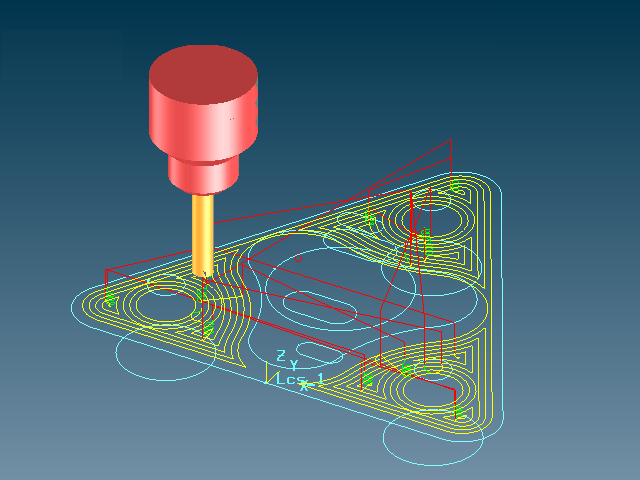
Milling Strategies
CAM for 2.5 to 5-axis milling
Every CAM function of EUKLID CAD/CAM is designed to optimize the machining process. The wide range of machining strategies, from 2.5 to 5-axis milling, satisfies the needs of even the most experienced user.
EUKLID CAD/CAM calculates optimized milling paths for 2.5 to 5-axis milling. Furthermore, the Milling Assistant supports all machining parameters for your NC programs and allows the easy integration of the company’s own know-how.
All functions may be used for automations and programming of family parts. EUKLID CAD/CAM creates process- and time-saving NC programs ensuring the defined surface quality. The collision control takes not only the work piece into account, but also the holder and tool.

Milling Assistant
The EUKLID Milling Assistant (MAS) offers an independent, highly comfortable machining environment, controlling complete NC machining from the slug to the creation of NC data.
The Milling Assistant clearly separates the machining steps defined from their calculation. The user defines all machining steps in neatly arranged forms and then starts the calculation. The calculation may be repeated as often you like. The Milling Assistant’s forms allow the modification of all parameters. The following recalculation will recognize and recalculate only the steps influenced by the entered modifications. This enables you to easily create company-specific variants of Milling Assistant projects.
Master project
The EUKLID Milling Assistant makes it extremely easy to calculate family parts. In the Milling Assistant, just change the geometry file and EUKLID CAD/CAM will automatically calculate new milling paths, according to the parameters set in the Master Milling Assistant.
Repeated patterns
Repeated, identical sections of a NC program are calculated only once and then transformed in less than a second: moved to another place, mirrored, rotated or duplicated.
The EUKLID Milling Assistant offers all possible transformations:
- duplicate
- move
- rotate
- mirror
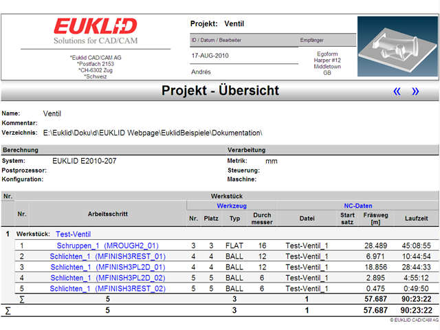
Documentation
EUKLID CAD/CAM’s milling documentation offers detailed information about the machining sequences, including every step, in convenient HTML-format.
The EUKLID Milling Assistant reads all necessary data from the given NC programs. The following graphs and tables are shown:
- Administrative data (project name, user, client…)
- Table of contents
- NC data (program number, start point …)
- List of tools used (milling length, time of use for each tool)
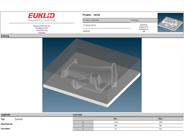
- Workpiece geometry, slug
- Every individual working step (roughing, semi-finishing, finishing)


Applications
EUKLID offers intelligent solutions for numerous standard applications.
2.5 axis
With 2.5-axis machining, as defined, two axes move simultaneously, the third axis (“.5”) serving as the feed axis.
Contour controlled 2.5-axis machining includes:
- Pocket milling (may be multiply nested)
- Real contour milling, that means, tracing curves
Furthermore, multiple drilling and milling cycles are offered, such as centering, drilling, reaming, thread cutting, rectangular pocket milling, groove milling and circular pocket milling.


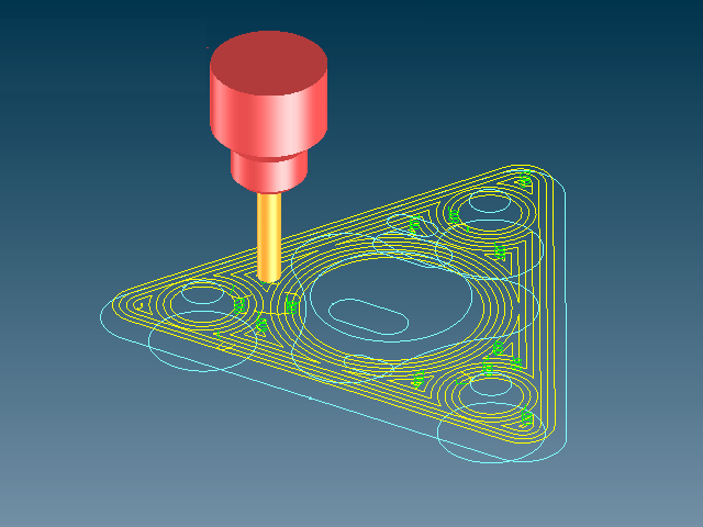
2.5-axis milling
Excavation and contour milling of pockets and contour milling of curves.
Pocket milling:
- The pocket contours are defined by 2D-curves.
- The pockets may be nested.
- With one call, an arbitrary number of pockets may be machined.
- Each pocket can include islands at various heights.
- Cascades of pockets and islands (stepped tapering) are allowed.
- Island levels are automatically machined.
Contour milling:
- Simple or complex 2D-curves
- The curves are traced directly or on one side
- Open or closed curves

Drilling and milling cycles
EUKLID supports the drilling and milling cycles offered by the NC control.
A wide range of drilling and milling cycles are available:
Drilling, counterboring, countersinking, deep drilling, reaming, thread cutting, rectangular pocketsmilling and circular pocket milling (G73, G81, G82, G83, G84, G85, G86, G87, G89). If an NC control ignores a cycle, the postprocessor will create the necessary commands (known by the NC command) for this cycle.
Hint: See Drill Features.
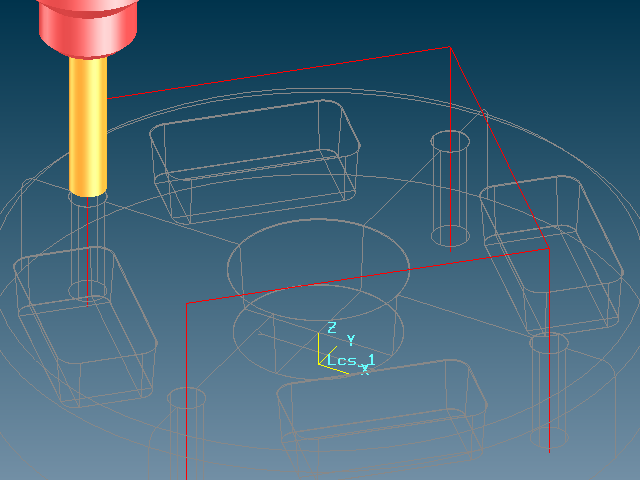


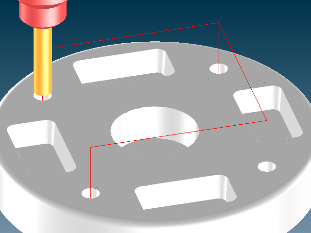
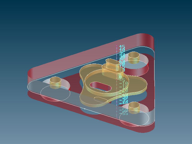
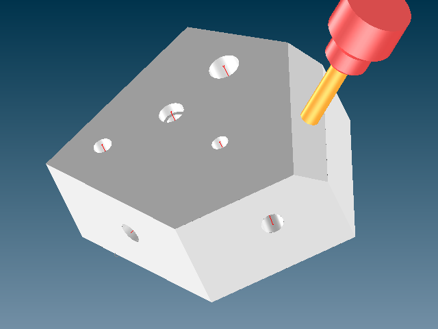
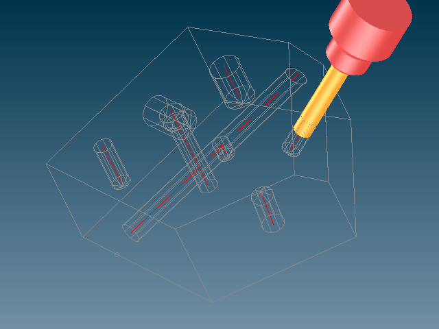
Drill features
EUKLID’s drill features program easily recognizes all bore holes present in a workpiece.
Then the drilling cycles are executed, automatically machining all these bore holes.
With a 5-axis milling machine, the bore holes may be orientated in the space, as you like.
If necessary, machining sequences (centering, pre-drilling and finish drilling) may be defined, as you like.


3 axis
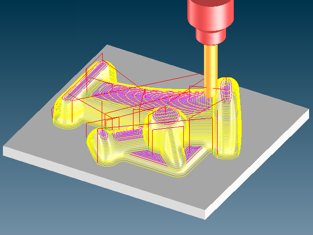
EUKLID CAD/CAM offers a wide range of 3-axis milling strategies, even a set axis (different to z-axis) is possible. These strategies allow you to achieve the desired quality. The residual material is automatically recognized and taken into account for the next machining steps.
All requirements are satisfied by these strategies. For example, you may define regions to machine them in a special way. Of course, all milling paths are collision free, even faulty surfaces or undercuts will never lead to injuries of the workpiece. The tool’s long service life and excellent milling surface are the result of such optimized milling strategies. To achieve that, the milling region gets separated in steep and flat zones. The transition angle, separating steep from flat zones, may be selected as you like.


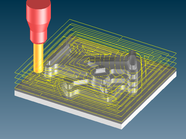

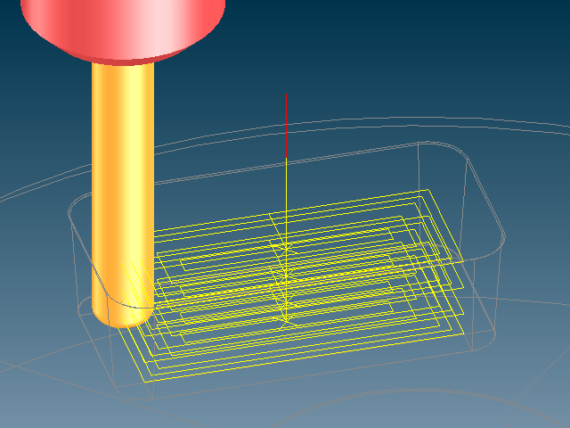
Roughing
Depending on the tool selected and material to be machined, several roughing methods are offered, including set axis (different to z-axis). EUKLID CAD/CAM’s highly flexible slug definition guarantees short machining times, avoiding unnecessary paths and machining paths in the air.
Automatic updating of the stock model allows several tools in a sequence, for optimum machining in shortest time. The tool paths may be rounded with free selectable radii, making them specially suited for HSC (high speed cutting) machining.
Result: Short machining times and long service times for the cutters.


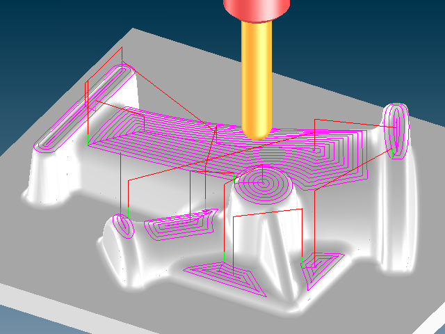
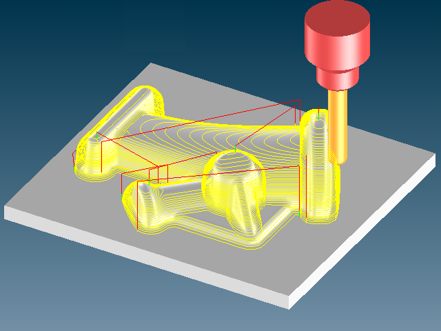
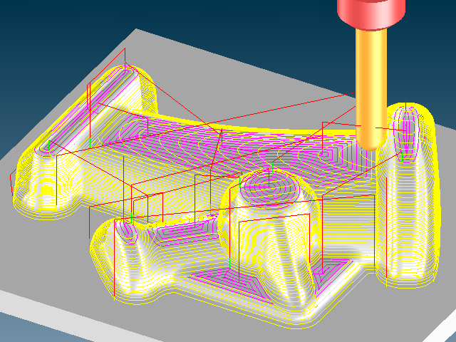
3-axis finishing
The extensive milling strategies offered by EUKLID CAD/CAM meet all your finishing demands: 14 main strategies and multiple secondary and rest removal strategies achieve the desired optimum results.
Most strategies divide the geometry into steep and flat zones. E.g. the main strategy may be used for the steep zones where this strategy works well, and the flat zones can be machined with the secondary strategy (or vice versa). The transition angle between the zones can be selected as desired.
Rest removal strategies: The residual surfaces (grooves), not millable with the biggest cutter, will be machined with one or a sequence of smaller cutters. The combination of main, secondary and rest removal strategy results in an excellent milling surface.


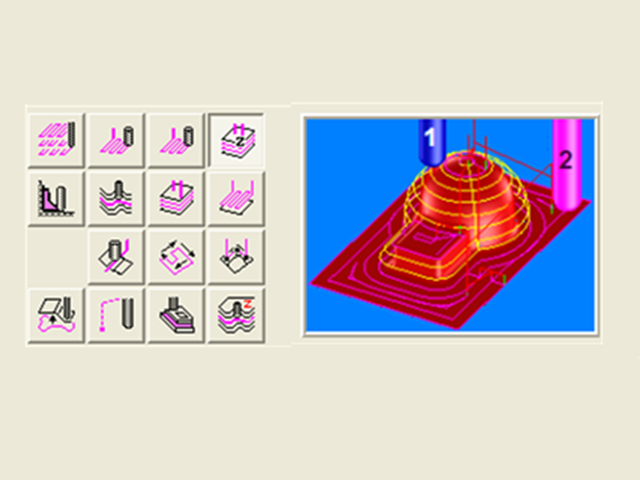
5 axis – One of EUKLID’s strengths!
EUKLID CAD/CAM offers a wide range of strategies for 5-axis milling, allowing users to consistently achieve the desired surface quality. All functions are designed to enable even beginners to produce a 5-axis milling program easily, while at the same time allowing sophisticated, complex machining.
For example, unmilled residual material is automatically recognized and taken into account for further processing.
The various milling strategies satisfy every requirement. As for the 3-axis machining, regions for special machining may be defined. Of course, all milling paths are collision free, even faulty surfaces or undercuts will never lead to injuries of the workpiece. It’s simple to control the cutter axis, making 5-axis milling easy.
The most important characteristics are:
- support for all cutter types (spherical, shaft, and torus cutters)
- surface-guided tool axis
- “quiet” axial movement through specification of an axis control geometry
- relative positioning angles (inclination and tilt angles)
- collision check and correction (linear and rotary)
- extended approach strategies
- milling of helical and spiral paths (helical milling)
5-axis roughing
Depending on geometry and the tools used, you may select from a wide variety of machining methods.Of course, any combination with 3-axis roughing is possible. EUKLID CAD/CAM’s highly flexible slug definition guarantees optimum processing with short machining times avoiding unnecessary paths and machining paths up in the air.
The automatically updated stock model allows roughing with several tools in a sequence, for optimum machining in shortest time. Using 5-axis roughing strategies generally results in very well prepared slugs, close to the geometry, avoiding long machining times.


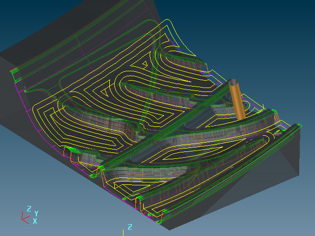
5-axis finishing
The extensive milling strategies offered by EUKLID CAD/CAM fulfill all your finishing demands: 16 main strategies and several secondary and rest removal strategies achieve the desired optimum results: The highly effective 5-Axis finishing with spherical, shaft, and torus cutters generally produces good surface qualities and is a core competence of EUKLID CAD/CAM. Many powerful milling strategies are offered:
- Finishing with milling paths calculation in parallel planes
- u,v-finishing
- Tracing single paths (groove tracing, region boundary tracing, contour projection tracing, or u,v polygon tracing)
- Point approach
- Milling 3-axis paths with 5 axis strategy
- Z-level finishing
- and finally: parallel to a guide surface
- as well as several roll-off strategies
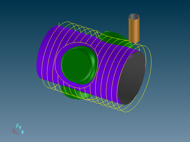
These wide-ranging milling functions fulfill every special demand. Some strategies are geometry-oriented; others use a guide surface to define the milling paths. Furthermore, there are special functions, for example to machine rotary work pieces.
Rest removal strategies:
The residual surfaces (grooves), not millable with the biggest cutter, will be machined with one or a sequence of smaller cutters. This combination of main, secondary and rest removal strategy results in an excellent milling surface and high surface quality.


Special Applications
With our extra modules for special applications, you can easily master even the most difficult machining cases.
Tire molds
EUKLID-Tire is EUKLID CAD/CAM’s industry-specific special module, generating in large extent automatically 3D-geometry and machining programs for complex tire profiles. One single function with few parameters is sufficient to describe tire profiles with mathematical precision.
A tire’s structure is quite complicated. The profile contains many individual ribs, positioned on a curved surface, making it impossible to create them with standard surface functions. Then the ribs are trimmed with each other, creating sharp convex edges and concave corners. Though it seems as if a tire profile consists of repeated, equal sections, in reality, each partial segment (pitch) has a different width, and contains compressed as well as stretched ribs.


Impeller
Impellers are highly complex workpieces which can only be milled with 5-axis machines. On the other hand, impellers are classic family parts. Their construction is always based on a very similar form, the same functionality and the same basic rules apply.
The specially developed EUKLID Impeller module considers base, top and blade surface and executes the complete calculation automatically, including the milling program. To generate the impeller milling program, the collision control due to minimum distance, cutter size, cutter draft angle and the necessary lead angle will be calculated. The lead angle avoids flaws that otherwise could be created by undercuts.
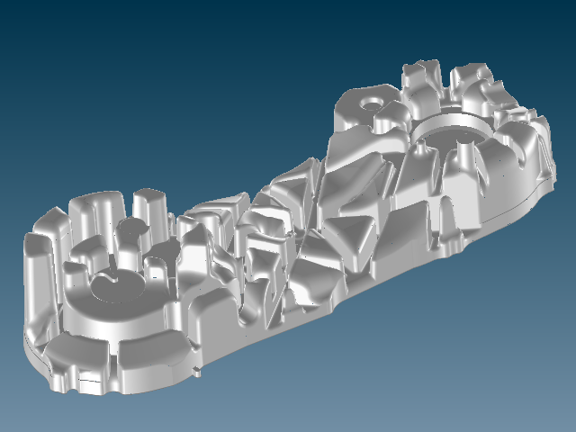
Forge module
Numerous individual functions of EUKLID Forge, each of them efficient and fast, support the user throughout the forge-specific tasks, including geometry-derivation of the preforging die and trimming tools. The most important functions are partial expansion and calibration.
To define the separation curve between upper und lower forging die is a most challenging task. The separation has to be calculated very precisely, in order to allow easy separation of the workpiece from the die, as well as to allow easy trimming of excess material from the forging. Depending on the workpiece, the separation process of upper and lower die is so complex that the separation curve can not be defined on a simple plane.
NC Data & Simulation
The central component of EUKLID CAD/CAM is the generation of NC data and the exact simulation of the same.
Postprocessor / NC data
With the help of our configurable postprocessor, the tool paths calculated by EUKLID CAD/CAM are transformed into machine-readable CNC data.
For each machine control interactive setting, the EUKLID post processor allows adjustments for 2,5 to 5-axis machining. EUKLID CAD/CAM also supports parametrical position-controlling of the 4th and 5th axis. Postprocessors for rare or exotic control types may be provided, as well as for unique individual controls.
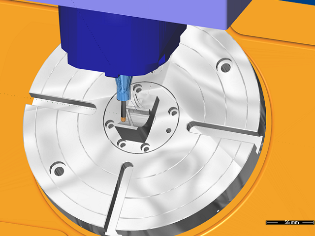
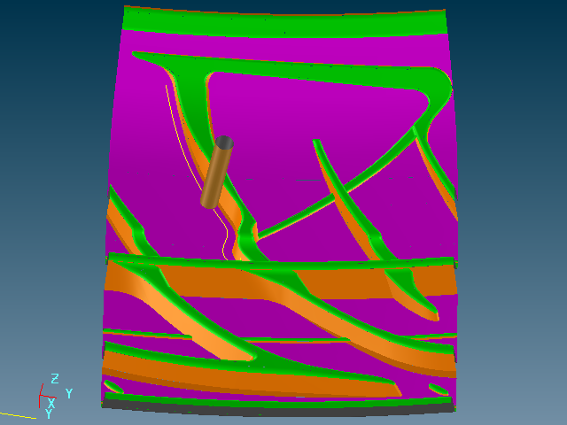
Simulation
The simulation offers detailed control of the machining process: visual, numerical and collision controlled. EUKLID CAD/CAM milling simulation includes cutting simulation as well as machining simulation.
Material removal:
Starting with the slug and using the NC data, the removed material is calculated, and the remaining material is plotted and collision controlled.
Machining simulation:
This simulation considers the movements of the milling machine itself. This control is extremely important for 5-axis milling.


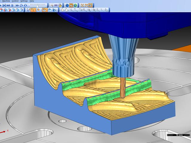
Cutting simulation
The cutting simulation starts from the slug, calculating and showing the whole milling process in detail. EUKLID CAD/CAM offers a 3-axis as well as a 5-axis cutting simulation module.
The extensive analytical functions simulate and control:
- the slug
- the workpiece (part)
- teh tool
- the holder
Preventing collisions and showing the results graphically and in numeric tables. Though many parameters may be set to influence the cutting simulation, it is still simple and intuitive to understand.


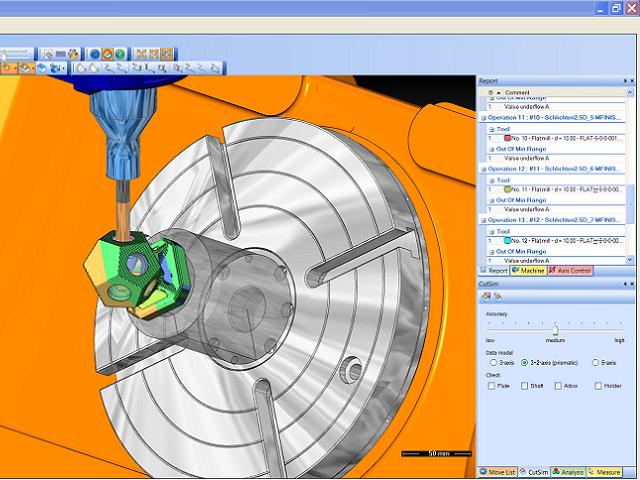
Machine simulation
EUKLID CAD/CAM’s machine simulation offers detailed control of every machine movement: visual, numerical and collision controlled. This control is extremely important for 5-axis milling.
The machine simulation may control 3-axis or 5-axis machining, checking the following points:
- Slug with machine, tool and holder
- workpiece (part) with machine, tool und holder
- as well as the machine position
Though many parameters may be set to influence the machine simulation, it is still simple and intuitive to understand.


Related products
-
Sale!

ZEISS CALIGO 4.4.1 cracked version
Original price was: 200 $.140 $Current price is: 140 $. Add to cart Quick View -

Primtech 16 cracked license software
150 $ Add to cart Quick View -

MazaCAM CAD/CAM and Editor – Matrix Edition Version 4.6
160 $ Add to cart Quick View -

PointSense Total Package cracked version
200 $ Add to cart Quick View -
PhoToPlan Ultimate cracked version
160 $ Add to cart Quick View -
BySoft 7 version 8.4.0 full cracked ready for download
160 $ Add to cart Quick View -
Sale!
Intergraph CADWorx 2017 R1 cracked version
Original price was: 180 $.150 $Current price is: 150 $. Add to cart Quick View -
Leica Cyclone 9.3.2 cracked version
150 $ Add to cart Quick View -

CADMATIC 2016Q1 (Diagram, Hull, Outfitting, Plant, Design) cracked
130 $ Add to cart Quick View -

MiriSys Software Suite (all modules\tools)
230 $ Add to cart Quick View