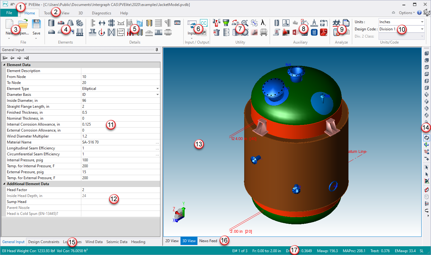
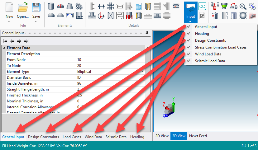
PV Elite breaks a vessel into an assemblage of individual elements—heads, shells, cones, body flanges, and/or a skirt—and the components on these elements. A quick look at the screen above shows the data (11) defining one element in the graphic view (13). Except for From Node and To Node, the data is common to all vessel wall thickness calculations. The From Node and To Node inputs are necessary to assemble the individual elements into the complete vessel and are automatically assigned by PV Elite. A complete vessel is required if all dead and live loads are to be included in the design or analysis. However, PV Elite will run wall thickness calculations on elements without constructing the entire vessel.
The body of the screen contains either two or three areas – a table of the Element Data (11), a table of the Element Additional Data (12) and the graphic area which contains an image of the current status of the entire vessel or the current element (13). A status bar displays (17) across the bottom of the screen and displays the element count, the position and orientation of the current element, quick internal pressure calculations for the current element.
When you click in the data areas (11 and 12), the Tab key moves the highlight (and control) through its input cells. In most element data areas, press Enter to register the data and move the focus to the next field. The exception is at combo boxes where clicking the arrow displays the available choices. Throughout the software, F1 displays help for the highlighted data item. After you are familiar with these screen controls, a combination of mouse and keystroke commands will provide the most efficient navigation through the software.
Some of the data input in PV Elite is controlled through a data grid (11 and 12). To enter the data, click the mouse on the data text, such as Inside Diameter, and type the input value. The cursor will not blink over the numeric/alphanumeric values until typing has begun. After the data is entered, press Enter or Tab to proceed. The arrow keys can also be used to navigate between the input fields.
 The right mouse button is used to select vessel details on the vessel graphic. Combo boxes have the down arrow button at the right end of the input cell.
When the 3D View (13) is active, a few more keys are available. No special highlight appears, but the string PgUp/PgDn/Home/End displays at the bottom graphics area. This indicates that these keys are now active. The image in the graphics area shows the current state of the input for the vessel model with its elements and the details on these elements. Switch between 2D and 3D views using the tabs at the bottom of the screen (16).
When the 2D View is active, one of the elements is highlighted. The Element Data and Element Additional Data sections (11 and 12) define this element. By pressing Page Up or Page Down, the highlight changes from one element to the next through the vessel. Press the Home and End keys to move the highlight to the first and last elements in the vessel. Also, you can click the left mouse button while selecting the element to highlight it. After an element is highlighted, detail information for that element may be accessed. With the mouse, click the right mouse button for the existing detail image to display. To add details to the current element, click the appropriate detail on the Details panel (5) and enter the necessary data.
The News Feed contains product information, such as the latest product version. In addition, you can refer to the page for upcoming events, product training opportunities, and future webinars. You can use the quick icon links at the bottom to get to the product web pages, the latest newsletter/blog postings, and Intergraph CAS social media sites.

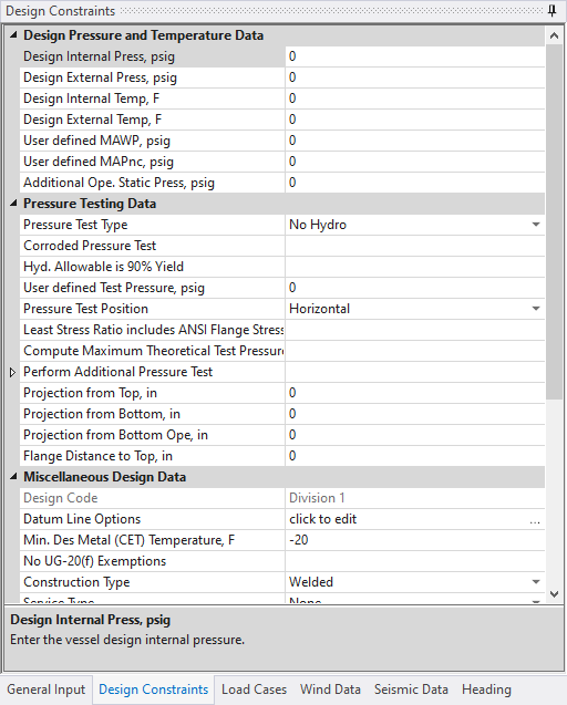
 items are used to define the other types of data that might be necessary for an analysis: design constraints, report headings, general input data, and live (
 option allows you to enter data and analyze without building a vessel. These are Intergraph’s CodeCalc analysis modules, some of which are not incorporated directly into PV Elite. CodeCalc, Intergraph’s popular vessel component analysis package is included in PV Elite.
 .
.