
3D-Dig fully cracked version
$ 170.00
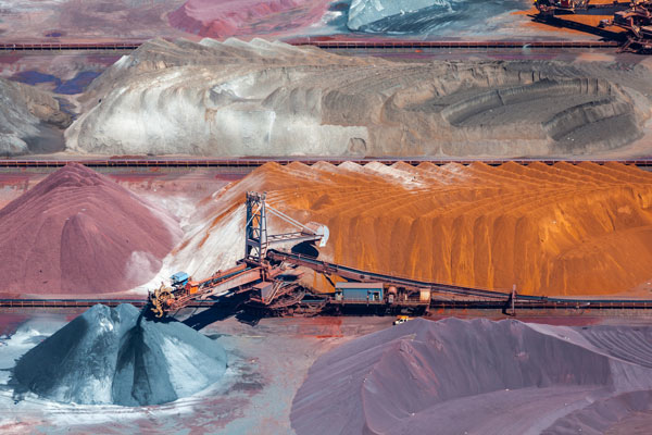
3D-Dig simulates mining processes — excavation, transport and dumping — bucket-load by bucket-load.
3D solutions for every mining operation ensure that your mine plan will run smoothly, before you implement. Mining software solutions proven over 25 years, for even the most complex operations.
Description
Mining simulation
3D Simulation of Mining Processes – Excavation, Transport and Dumping.
The flexible modelling system allows for highly detailed incremental simulation conforming to a schedule.
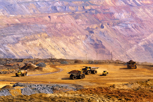
- Fleet productivity for draglines, truck-shovel and dozer systems is supported with full dynamic simulation of equipment using haul/transport routes.
- Detailed animations are produced for the operation which may be run independently on any PC, tablet or smart phone.
- 3D-Dig animations are readily understood by mining personnel of all backgrounds, as well as non-experts.
- Detailed volumetric and productivity reports are produced including calendar timing.
- Topographic models of the operation at any stage of the schedule can be produced and exported.
- Selective dumping (material modelling) is supported, including stratified dumps.
Manuals
The system comes with comprehensive online manuals as well as extensive training material and resources.
Generic and Topographic Simulation
Simulate your earthmoving
This is 3D-Dig’s terrain modelling “engine”. It also contains functionality for modelling excavation and dumping in defined areas, and many very useful add-ons. Unlike conventional systems which model excavations and dumps according to predefined geometry, 3D-Dig allows excavation and dumping to be simulated in small increments similar to the excavation and dumping processes implemented by mining machinery. This module forms the base for all other 3D-Dig Modules.
Software provides rich functionality
-
Rapid dynamic 3D visualization
- Smooth hardware rendering of topo and mining machinery uses the latest OpenGL graphics engine.
- Interactive 3D graphics allows easy manipulation of design elements.
- Advanced display options include rendering of layers exposed on terrain, contours superimposed on rendered views, and slope-based coloring of the terrain grid.
- Multi-step undo and re-do for all functionality facilitates interactive design.
-
Surfaces and layers
- Detailed modelling of mining geometry uses multiple surfaces above and below the topo.
- Layers formed between surfaces readily model ore and waste, including ore lenses.
-
Earth moving — excavation, multi-stage dump design and optimization
- Flexible excavation from topo to any surface is done within a polygon, with variable batter angles.
- Additional constraints such as surfaces, can be applied to any excavation.
- A unique dump algorithm calculates the spread of dumped material on any topo, load by load.
- This dump algorithm rapidly simulates multi-stage dumps, allowing maximum material fit and minimized transport inefficiencies to be determined.
-
Logging of swell and material in user-defined logs
- Volumes of excavated and dumped material are saved to internal tables (material logs).
- Swell and density of blasted and excavated material is recorded along with these volumes.
- Material log tables can be exported to Excel for further processing and reporting.
-
Tracking and separately reporting prime and re-handle
- Material not previously dumped (i. e. prime material) is accurately separated from previously dumped material (i. e. re-handled material), during each excavation.
- Areas of the topo can be marked as previously dumped (i. e. re-handled) material.
-
Rapid planning of roads, ramps and drains
- A point-and-click interface for horizontal and vertical alignments allows rapid design of roads, with detailed reporting of cut and fill material.
- The same interface works well for creation of ramps and drains on the topo.
-
Blast wizard
- A user-defined two-dimensional blast profile is applied along a section of topo, to simulate the effect of blasting in three dimensions.
- Local mass balance and correct treatment of swell ensure an accurate, real-life result.
-
Online help
- An on-line explanation of the parameters in each dialog box (accessed through the F1 key), is available for most of the dialog boxes in Generic Simulation.
- Detailed description of functionality, along with training and tutorial material, are available through an internet-based online system.
Manuals
The system comes with comprehensive online manuals as well as extensive training material and resources.
The 3D-Dig mining simulation modules
3D-Dig benefits and applications
- Life-of-mine landform and spoil transport analysis.
- Optimization of pit design, scheduling and spoil placement.
- Troubleshooting studies targeting issues such as access and spoil fit.
- Researching and validating new and novel mining methods.
- Highly effective communication tool, for both corporate and field communications.
- Assists and supports equipment purchasing and upgrade decisions.
- Improved allocation of waste to different equipment types.
Single-Step Dragline Simulation
Simulate your draglines
This module uses a detailed model of the Dragline to calculate material movement and productivity of a single dragline excavation linked to a dragline dump. Each major dig step is modelled in a manner that conforms to the limitations of the dragline geometry. For each step, the excavation and dumping progress incrementally. This is the traditional dragline simulation for which 3D-Dig is well known.
Valuable communication tool
-
Both Detailed and Approximate Modelling
- The dragline simulation system allows both detailed and approximate modelling of dragline operations.
- The system constantly checks dig depth and dump height.
- Detailed simulation progresses with the user positioning the dragline at each dig location.
- Approximate simulation, suitable in steady-state areas of the pit, progresses with multiple blocks excavated and dumped simultaneously.
- Prime and re-handle volumes are recorded on a block by block basis.
-
Productivity Calculated
- During the operation, the system optionally calculates productivity based on:
- machine geometry,
- motor characteristics,
- detailed simulation of bucket trajectories.
-
An Animation Video
- On completion of a dragline simulation, an animation video is created detailing the operation.
- These videos provide a valuable communication tool, showing both details and overall concepts to planners, operators and management in an intuitive way that is easy to understand.
Auto Excavation and Dump Sequencing
Automate your earthmoving simulation
This module is an invaluable tool for visualizing various development scenarios and transport distances, for testing order of development and visualizing interaction of excavations and dumping volumes. Once a simulation is set up, substantial modifications to the dumps can rapidly be implemented and the simulation re-run.
Optimize dumps
-
A dump hierarchy
- Excavation is automatically executed according to a schedule generated within 3d-Dig. Material reports automatically to a dump hierarchy. This module is invaluable for visualizing various development scenarios, testing order of development and visualizing interaction of excavations and dump volumes.
- Development sub-sequences can be excavated in any order. A hierarchy of dumps can be assigned to each sub-sequence and a pre-set productivity can be assigned to each subsequence/dump combination. This pre-set productivity controls the progress of the simulation of the super-sequence.
- Development sub-sequences (each a contiguous series of mining blocks) can be excavated in any order. Just by changing a few parameters, complex multi-stage dumps are rapidly re-build and re-simulated.
- In most mining simulation models dumping with predefined dump geometry subdivided into blocks. 3d-Dig however simulates dumping from first principles. Dumps can be constrained by geometric models but the dumping process is simulated by modelling material flow.Once the simulation is set up the dump model can be rapidly changed and the simulation rerun. 3D-Dig can simulate the incremental dumping of equipment such as draglines and bulldozers. Hence dumps can be automatically generated which are a function of the equipment and operating method.
-
A super-sequence
- Sub-sequences are assembled into a tree, called a super-sequence. A hierarchy of 3D-Dig dumps can be assigned to each sub-sequence and a pre-set productivity can be assigned to each subsequence/dump combination. This pre-set productivity controls the progress of the simulation of the super-sequence. Dumps are constructed via simulation using the 3D-Dig Dump Algorithm.
- This method does not require a block reserves model of the dump. Consequently, once a simulation is set up, substantial modifications to the dumps can rapidly be implemented and the simulation re-run. As a dump in a hierarchy fills, dumping automatically switches to the next dump in the hierarchy.This module is an invaluable tool for visualizing various development scenarios and transport distances, for testing order of development and visualizing interaction of excavations and dumping volumes.
-
Related Modules
- The Automated Excavation and Dump module is required by the Truck/Shovel Simulation and Optimization module and the Automated Dragline Simulation module.
Automated Dragline Simulation
Automate your dragline simulation
This module simulates complex multi-pass Dragline Development. This is done by breaking the development into sub-passes, with a number of Dragline Moves carried out in sequence in each sub-pass. This simulation builds on the Single-Step Dragline Module and the Automated Excavation and Dump Sequencing Module. Dragline Bench, Arc Area and Boom Dumps and Dozer Bench Dumps can be assigned to each Move. Once a Dragline Simulation is set up, users can easily change parameters to find an optimal development strategy.
Optimal development strategy
-
Design multi-pass dragline strip
- The Automated Dragline Simulation system automates the design of a complete, multi-pass dragline strip.
- While the system does not simulate the full detail of each block as performed by the dragline operator, block sized segments of the pit are simulated in sufficient detail to calculate prime and rehandle volumes and to assess spoil fit.
- Steady state sections of a strip are modelled with accuracy similar to a manual 3D-Dig modelling exercise.
- Ramps and endwalls are modelled in an approximate manner. However the system has the ability to pause when approaching these situations. This allows the user to continue manually if necessary, then re start the automated process.
-
Subpasses and supersequences
- Setting up a strip for automated dragline digging is initially very similar to setting up for Automated Excavation & Dump simulation.
- Subsequences are replaced by Subpasses and combined into a Supersequence. Each block in a Subpass is used to form a Modelling Block.
-
Dragline steps, moves and procedures
- Each modelling block will consist of several (as many as the method requires) Steps. A Step is the basic increment of the full set of moves required to excavate a complete modelling block for a given pass or sub-pass. Each step consists of an excavation and a dump. The number of Steps and the geometry of the associated excavations and dumps vary with the operating method.
- Excavation Steps extend, parallel to the pit, for the full block length. Dump Steps will extend as required in a manner that ensures dumping takes place within the draglines reach. A complete set of Steps sufficient to complete a full modelling block of a given pass is referred to as a Procedure. Procedures are applied to Subpasses.
-
Easily change parameters
- Once a Dragline Simulation is set up, users can easily change any parameters to find an optimal development strategy.
Truck and Shovel Simulation
Simulate your earthmoving by truck and shovel
Full simulation of truck and shovel operations is conducted. Material is automatically excavated and dumped in accordance with a schedule. Each increment is simulated with a haul route connecting excavation and dump. This module adds Truck and Shovel simulation to the Auto Excavation and Dump Simulation module.
Optimize truck assignment
-
A network of roads
- A network of roads (Main Haul roads and Access roads) can be linked to the excavations and dumps. Virtual roads can be used for some or all roads for more rapid estimation. Productivity is calculated using a realistic truck/shovel productivity model.
- Once the model is calibrated, users can readily vary Truck fleet assignment to achieve optimal development goals. The simulation can also optimize truck assignment by auto-assigning trucks to each block to achieve a user-assigned percentage of maximum productivity.
-
Super-Sequence schedule
- The super-sequence tree is made up of sub-sequences. To generate sub-sequences:
- Users begin by defining block lines for each region to be excavated i. e. each pit.
- Users then define the series of surfaces to which excavation takes place.
- Initially a «Raw Sequence» is generated, temporarily excavating all blocks in order, for all passes and lifts.
- Sub-sequences are then generated and combined into the super-sequence tree, using 3d-Dig’s Super-sequence Editor.
-
Easily optimize dumps
- There is considerable flexibility to allow changes in the simulation set-up and key parameters, so that the simulation can be re-run, without having to set everything up again.
- Sub-sequences can be edited to encompass different block ranges.
- Changes to the super-sequence tree can easily be done using the super-sequence editor.
- Excavators, Roads, Trucks, Dumps are assigned to sub-sequences.
- Because of the way 3D-Dig dumps are simulated, changes can readily be made to the dumping.
- This includes changing all the passes, lifts, final surfaces, footprints etc. for Staged Dumps.
Bulldozer Simulation
Simulate your earthmoving by bulldozers
This module simulates a complex Dozing operation by breaking it into Dozing Regions. Each Dozing Region has a single overall direction of push by the Dozer. A preliminary Transport Analysis calculation can be carried out to help users set up optimal Dozing Regions. Dozer productivity is calculated using standard rim-pull curves that can be scaled by the user. Intermediate dozing surfaces are calculated to guide the operation of the Bulldozer from the initial (current) terrain shape to a final shape that is input by the user. These intermediate surfaces are optimized to maximize Dozer productivity.
Maximize productivity
-
Regions and surfaces
- 3d-Dig Bulldozer performs a fully three-dimensional simulation of the dozer operation. The simulation starts with the pre-dozing surface and the user imports or generates a final target surface for the dozing operation. The system then simulates the excavation and dumping of the dozer operation on an incremental basis. Increments are generated longitudinally using automatic dozing regions and vertically using automatic surfaces. For each increment the dozers path is determined and speeds and productivity derived from the bulldozers speed versus rimpull curve.
-
Parameters and productivity
- Many parameters can be rapidly varied such as dozing angles, pivot/bridge geometry as well as final target surface. On completion the simulation reports the following:
- Overall prime volume.
- Overall rehandle volume.
- Total execution time.
- Bulldozer productivity.
- Any areas with insufficient spoil room.
-
Important effects
- As the system is fully three-dimensional, important effects such as longitudinal spoil movement between regions and localised spoil conditions based on pre-dozing topography are correctly taken into account by the simulation.
- Once a simulations is set up the user can rapidly change the dozer target (design) surface. This change can involve either increasing or decreasing the elevation of the surface or substantially changing its geometry.
Dragline/Pre-Strip Integration
Optimize your pre-stripping
This module calculates the results (surfaces, volumes) from a multi-strip Dragline operation. A pre-strip horizon and a spoil profile are calculated for each strip, taking into account the material that must be moved outside the pit by truck/shovel before the dragline operation. Multiple strips of dragline operation are simulated, taking into account Parallel and Perpendicular Ramps included in the calculation. Excavated coal volumes are also calculated and logged block-by-block for each strip.
Quick & accurate long term plan
-
Spoil dumps
- Other functions allow the rapid design of spoil dumps to accommodate pre-strip material and in conjunction with other modules the life of pit can be modelled incrementally block-by-block and strip-by-strip.
-
Profiles
- A Strip Line Generator can generate approximate Dragline Strips. Strip lines can also be imported as DXF data. Users mark out the pit boundaries in each strip. They can then rapidly set up profiles for the Low Wall and High Wall geometry in different parts of each pit.
-
Pit shell
- Parallel and Perpendicular Ramps can be included in the calculation through parameters describing the ramp geometry and the inner surfaces used to construct the ramps.A pre-strip horizon is first calculated for each strip, taking into account the material that must be moved outside the pit by truck/shovel before the dragline operation. The simulation then calculates the Pit Shell for each strip (i. e. the excavated strip with its Low Wall and High Wall). Excavated coal volumes are also calculated and logged block-by-block for each strip.
Schedule Simulation
Optimize your schedule execution
Excavation is automatically executed according to an external schedule imported into 3D-Dig. Different material types are tracked. Dumps are assigned according to material type, position and excavation period. Material automatically reports to the dump hierarchy as the schedule is executed.
Optimize dumping
-
Visualization and testing
- The purpose of this module is to model digging and dumping of an external schedule imported into 3D-Dig. Multi-stage dumps are constructed via simulation using the 3D-Dig Dump Algorithm.
- This module is invaluable for visualizing various development scenarios and transport distances, testing order of dumping and visualizing interaction of excavations and dump volumes.
-
A hierarchy of dumps
- Blocks are excavated as specified by the schedule. A hierarchy of dumps can be assigned to each group of blocks. For assignment to dumps, schedule blocks are grouped according to:
– schedule period
– material type
– position in the pit - Just by changing a few parameters, complex multi-stage dumps are rapidly re-build and re-simulated.
- In mining simulation, dumping is usually modelled using a predefined dump geometry subdivided into blocks. 3D-Dig however simulates dumping from first principles. Dumps can be constrained by geometric models but the dumping process is simulated by modelling material flow. Once the simulation is set up the dump model can be rapidly changed and the simulation rerun.
- 3D-Dig can simulate the incremental dumping of equipment such as draglines and bulldozers. Hence dumps can be automatically generated which are a function of the equipment and operating method.
- Blocks are excavated as specified by the schedule. A hierarchy of dumps can be assigned to each group of blocks. For assignment to dumps, schedule blocks are grouped according to:
-
A flexible internal format
- Imported schedules are converted to a flexible internal format. This allows a wide range of schedule formats to be supported by 3D-Dig.
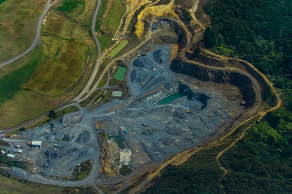
Environmental Reshaping
Optimize your mine rehabilitation
This Module reshapes a given region of the terrain to achieve a slope which is less than a user-input slope. The post mining topography can be reshaped in a manner that conforms to design slope criteria, balances cut and fill and minimizes transport distance. Further analysis of the resulting surface is provided through Transport Analysis and Drainage calculations.
Best transport for reshaping
-
Rapid reshaping with visualization
- Reshaping is carried out within user-defined polygons.
- The terrain within each polygon is redrawn as the reshaping is done. In this way, the automatic reshaping calculation is visualized and monitored as it progresses.
-
Optimal transport arrows
- A Transport Analysis calculation is included in this module. This calculates the optimal transport of material from the current surface to the final reshaped surface.
- A set of transport vectors indicating optimal spoil movement is produced. A summary table of volumes and transport distances is output to a spreadsheet.
-
Pumping ponded water
- Drainage and Ponding calculations allow calculation and display of catchment areas and ponding.
- Ponding volumes are calculated in user-specified areas on the terrain.
- A flexible water pumping times calculation is provided. Times may be output to a spreadsheet.
-
Visualization tools
- Visualization tools guide each stage of the reshaping design process.
- Using these tools, designers can easily optimize material transport and water flow for reshaping.
Related products
-
Nikon CMM-Manager 3.5 cracked
$ 180.00 Add to cart Quick View -

AP100US 20.7 (full cracked software)
$ 170.00 Add to cart Quick View -

PTC Creo Elements/Direct Modeling 20.6 cracked release
$ 140.00 Add to cart Quick View -
XSite v3.0 cracked license software
$ 160.00 Add to cart Quick View -
PhoToPlan Ultimate cracked version
$ 160.00 Add to cart Quick View -
Sale!
Intergraph CADWorx 2017 R1 cracked version
Original price was: $ 180.00.$ 150.00Current price is: $ 150.00. Add to cart Quick View -
PointSense Total Package cracked version
$ 200.00 Add to cart Quick View -
AstroCAM Series (full cracked software)
$ 160.00 Add to cart Quick View -
TachyCAD (Archaeology and Building Survey) cracked
$ 160.00 Add to cart Quick View -

JMAG-Designer v24 full cracked version released
$ 170.00 Add to cart Quick View