

BEASY Corrosion Defence V10R15.2 full cracked license
220 $
BEASY Corrosion Defence V10R15.2 provides a great number of new and advanced features that will enable engineers to improve CP system performance and provide deeper design insight. The new release not only incorporates improvements and enhancements to the core BEASY Corrosion & CP and the BEASY Corrosion Related Signature software but also to BEASY GiD and the BEASY ICCP Optimisation tools.
Description
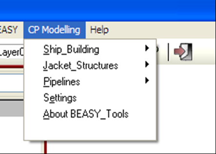
CP Modelling Menu
This new menu provides the user with a set of tools to help in Ship Building, Jacket Offshore Structures and Pipeline applications.
For Ship Building the new tools available allow the incorporation of anodes at specific locations on the hull orientated perpendicular to the ship hull and to include cuttings of any particular shape where dielectric shields with ICCP anodes or any other material on the ship hull can be defined.
For Jacket Structures the new tools include importing the jacket 3D geometry from an ASCII and IGES files. Visualising the 3D members in 3D (not as lines only). Trimming of the structural members to avoid intersections and yet preserve the surface areas. Cutting and removing the structural members above the sea surface. Organise members into different layers using the Diameter or a name given to a set of members.
For Pipelines the new tools facilitate the insertion of bracelet anodes along a pipeline.
Visualisation
The contour display list of results has been improved to simplify the interpretation and identification of the materials and location. Results are displayed in layers which are labelled with the group name and the label used for the polarisation curve applied appears in brackets. This simplifies the selection of layers to visualise the desired results making easier the turning on/off of one particular layer, to visualise results on one particular group or material.
New Tools Have Been Added To The CP Desktop
The CP Desktop provides convenient access to the following tools:
- Offshore Tools
- Off Potential Wizard New
- CP Quick Launcher New
- Result Filter New
- Settings New
The Offshore Tools provide facilities to automate many of the tasks required for modelling of geometries with cylindrical members, like the structural elements in jacket type offshore structures.
They also provide the capability to manage the process of launching time stepping runs to simulate the impact of anode consumption, degradation of coatings, build-up of calcareous deposits and changes in polarisation due to water flow rate. When modelling anode consumption the mass loss rate over time is calculated with time and used to change the anode size during the time stepping process.
This OFF Potential Tool calculates off potentials at given observation points, based on the polarisation that the structure had when the CP system was turned off. This is particularly useful for pipelines and other underground structures where the OFF potential measured at a location can be predicted.
Electric Circuits
The user interface for the electrical circuit tool has been enhanced both in terms of appearance and functionality. The circuit panel now allows automatic connections to be generated along section of pipelines or any component sharing connection points for example.
It is also now possible to introduce independent circuits in the model, for example one consisting of three disconnected circuits. This feature allows the solution of cases with interference and stray currents occurring between different components or CP systems and can also be used with models consisting of multiple zones.
The modelling of electric potential and currents in return path circuits involving a controlled power supply where the output current has been specified has also been simplified. A current controlled power supply can now be connected to more than one point in a structure.
Multilayer Electrolytes
The overall robustness of the multi-layer modelling capability has been improved and zones can now be embedded in a multilayer zone. The multi-layer facility in BEASY provides a simple way to represent layers of electrolyte with different resistivity without the need to define elements on the interface between the layers. This is particularly useful for onshore applications to represent the soil profile characteristics.
Sacrificial Anodes
It is now possible to define a group which simplifies the specification of anode properties of a group of anodes of similar type.
If the shape type is specified then the software will simulate the change in shape of the anode during a time step, using the predicted anode mass loss rate. This feature can be applied for cylindrical or prismatic profile anodes with rectangular cross section.
Sacrificial anode data (utilisation factor, original mass, initial consumption factor) and the properties of the anode material can be specified in the CP Wizard.
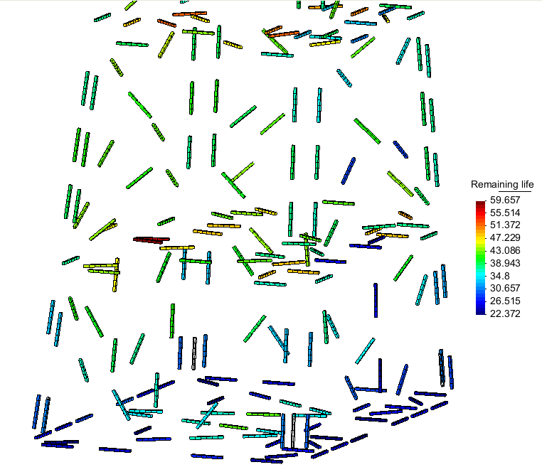
In BEASY GiD the predictions for the sacrificial anodes can now be visualised including the:
- Consumption Factor
- Current
- Mass loss rate
- Original mass
- Remaining life
- Remaining mass
- Time to zero mass
- Utilisation factor
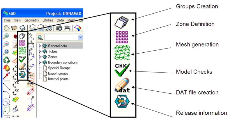
BEASY GiD
A new function has been added to the toolbar that checks the model definition ot groups and zones before saving a data file.
A set of geometrical operations that makes model creation easier and faster is now available. Functions are available to extend lines from one end point in the line direction, to create a line normal to a surface at a point, to create a cylinder from a centre line, and so on.
A new menu has been introduced allowing the automatic creation of BEASY groups from layers. This not only makes the model creation faster and easier, but also avoids the possible introduction of user errors when selecting entities to assign to groups.
The HELP System
New sets of tutorials have been added both covering material available in the previous releases and addressing the new features. Contents have been re-organised to facilitate navigation through the documentation system and a search engine is now available.
ICCP Optimisation
It is now possible to run the optimisation tool to predict coating damage in a structure such as the hull of a ship based on measurements of potentials. The possible optimisations which can be performed are summarised in the table below.
|
Objectives |
Groups required |
|
Minimise the current at the anodes |
Anode, Metallic Surfaces |
|
Achieve uniform protection on surfaces |
Anode, Metallic Surfaces |
|
Minimise the surrounding electric field |
Anode, Metallic Surfaces, Field points |
|
Fix the surrounding electric field to a target |
Anode, Metallic Surfaces, Field points |
|
Predict condition of the structure using Reference Electrodes and Anode Data
|
Anode, Metallic surfaces, Reference electrodes, Coating sensors, Prediction surfaces, |
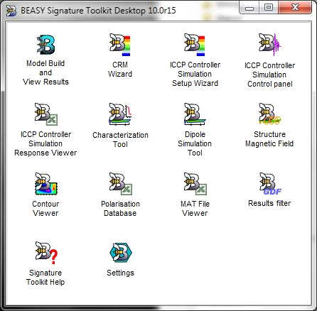
BEASY Corrosion Related Signature Desktop
The Signature Desktop (sometimes referred to as CRM) provides the access to the tools which can be used to predict and assess the corrosion related electric and magnetic signatures.
The tools available on the desktop are:
- CRM Wizard
- ICCP Controller Simulation Set Up Wizard
- ICCP Controller Simulation Control Panel
- ICCP Controller Simulation Response Viewer
- Characterization Tool
- Dipole Simulation Tool
- Structure magnetic Field
- Contour Viewer
- Polarisation Database
- Mat File Viewer
- Results Filter
- Signature Toolkit Help
- Settings
BEASY CRM
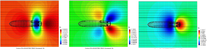
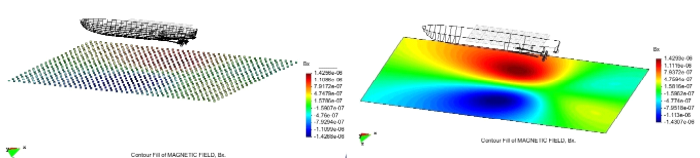
A new capability is provided to combine the results from the structure magnetic field tool and the detailed BEM model and visualise in BEASY Gid. The software saves the results in the gdf file and post-processing BEASY Gid files allowing the visualisation of the structural magnetic field and the combined magnetic field in 3D.
- Results that can be visualised in BEASY Gid include:
- Electric and Magnetic Field on observation points, lines or planes
- Structure magnetic field can be visualised
- Combined magnetic field ( Magnetic field due to current within the electrolyte plus Structural Magnetic Field)
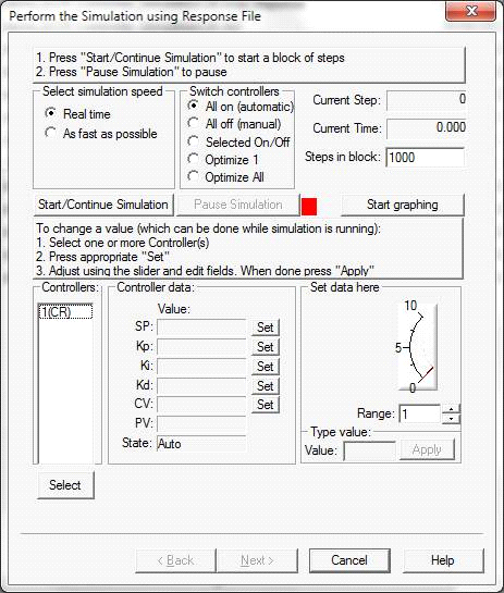
BEASY ICCP Controller Simulation
The ICCP Controller Simulation Tool has been reorganised to simplify the use of the tool and provide more capabilities. The tool is now divided into three tools which appear on the desktop.
- ICCP Controller Simulation Set Up Wizard
- ICCP Controller Simulation Control Panel
- ICCP Controller Simulation Response Viewer
The ICCP Controller Simulation Set Up Wizard all the controls necessary to be able to define the characteristics of the ICCP system and all the data required to define the properties of the ICCP Anodes, ICCP Reference Cells, ICCP Generators, ICCP
Controllers, and ICCP Sensors. Having completed the set up process the Control Panel can be used to simulate and visualise the response of the system and assess the impact of changes to the set points and controller parameters etc.
Related products
-
Sale!

SKM POWER*TOOLS FOR WINDOWS 7.0
Original price was: 10,000 $.150 $Current price is: 150 $. Add to cart Quick View -
Tebis V4.0 R4 full cracked version
150 $ Add to cart Quick View -
Sale!

DESIGN SUITE cracked version
Original price was: 8,000 $.250 $Current price is: 250 $. Add to cart Quick View -

Nikon CMM-Manager 3.5 cracked
180 $ Add to cart Quick View -

Micromine 2016 full cracked (all modules)
130 $ Add to cart Quick View -
Sale!

ZEISS CALIGO 4.4.1 cracked version
Original price was: 200 $.140 $Current price is: 140 $. Add to cart Quick View -

TAJIMA DG/ML 16 By Pulse Embroidery Design Systems cracked version
150 $ Add to cart Quick View -
GPR-SLICE v7.0 cracked radar software
160 $ Add to cart Quick View -
Sale!

Wilcom Embroidery Studio E3 Designing cracked with dongle emulator
Original price was: 3,000 $.110 $Current price is: 110 $. Add to cart Quick View -
Sale!

Intergraph CADWorx 2017 R1 cracked version
Original price was: 180 $.150 $Current price is: 150 $. Add to cart Quick View